
Power-delivery mechanism and apparatus of plasma-enhanced chemical vapor deposition using the same

a technology of plasma-enhanced chemical vapor deposition and power delivery mechanism, which is applied in the direction of chemical vapor deposition coating, electric discharge tube, coating, etc., can solve the problems of inability to meet the specifications of specific apparatuses, inability to manufacture, and inability to meet the requirements of special processes, etc., to achieve the effect of reducing the chance of wafer damage, facilitating the automation of wafer loading/unloading, and reducing the chance of wa

Inactive Publication Date: 2011-04-19
IND TECH RES INST
View PDF38 Cites 8 Cited by
  • Summary
  • Abstract
  • Description
  • Claims
  • Application Information

AI Technical Summary

Benefits of technology

Enhances productivity and yield by automating the loading / unloading process, reducing contamination risks, and allowing for precise adjustment of electrode distances within the PECVD apparatus.

Problems solved by technology

However, even until nowadays, the apparatuses used for manufacturing such products, such as PECVD apparatus, are still monopolized by only a handful of major manufacturers overseas that result in the apparatuses are so expensive that the average-sized companies can't afford them, besides, the specifications of those apparatuses might not be specifically designed to match perfectly with those special processes in solar power industry.
Thus, as the wafer's loading and unloading are not automatized but are performed manually, they will not only reduce the whole productivity, but also will contaminate the wafers and lower the yield possibly.
Although it is possible to use a robot in loading and unloading, but it is still not popular since the robot's high price and requires a considerable footprint to install the same.
Therefore, it is necessary to design an unexpensive and compact power-delivery mechanism that can be applied in a PECVD apparatus.

Method used


Image

  • Power-delivery mechanism and apparatus of plasma-enhanced chemical vapor deposition using the same
  • Power-delivery mechanism and apparatus of plasma-enhanced chemical vapor deposition using the same
  • Power-delivery mechanism and apparatus of plasma-enhanced chemical vapor deposition using the same

Examples


Embodiment Construction

[0026]For your esteemed members of reviewing committee to further understand and recognize the fulfilled functions and structural characteristics of the invention, several exemplary embodiments cooperating with detailed description are presented as follows.

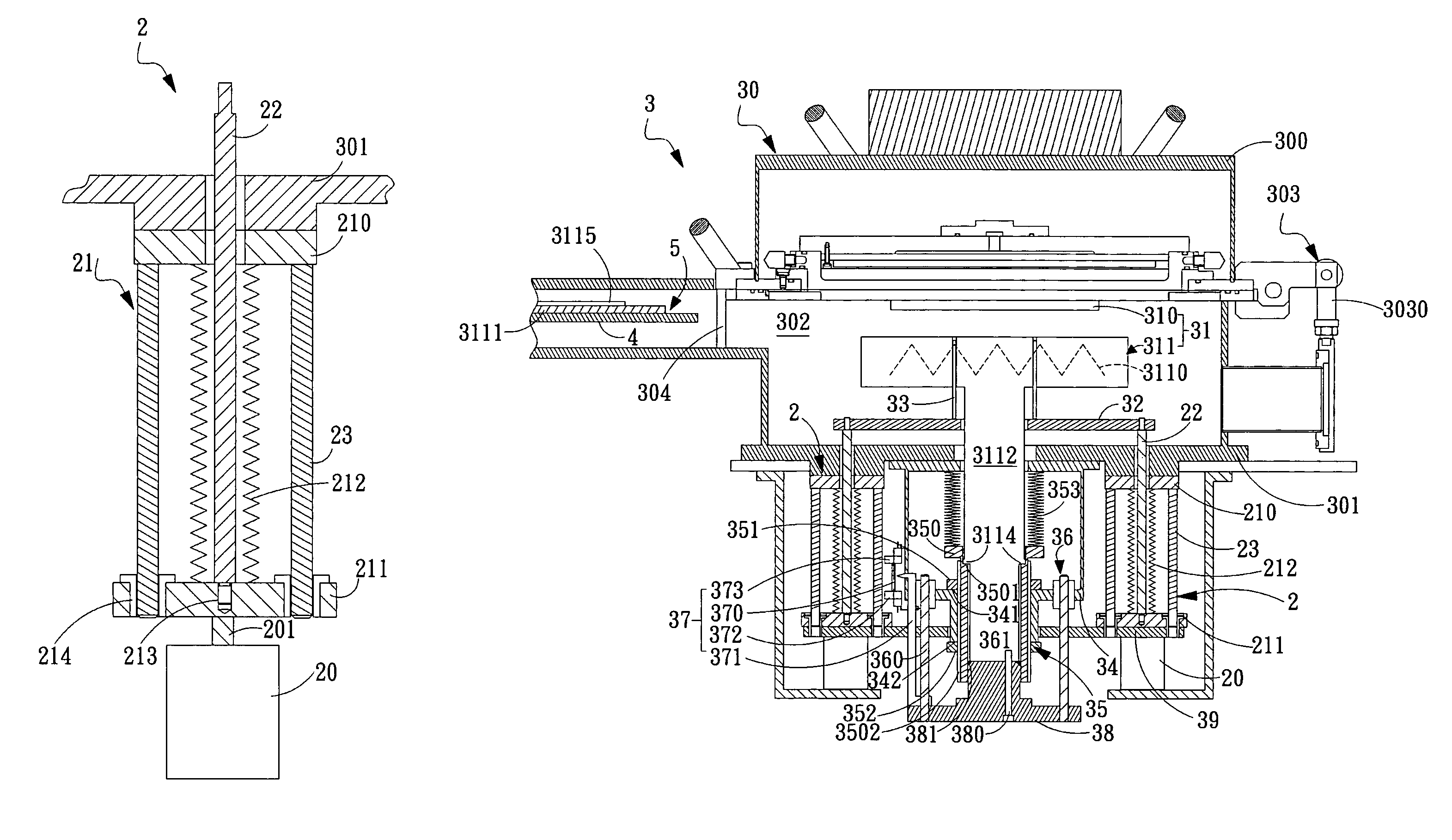
[0027]Please refer to FIG. 2A and FIG. 2B, which are two cross-sectional diagrams illustrating a power-delivery mechanism according to an exemplary embodiment of the invention. In FIG. 2A, the power-delivery mechanism 2 comprises: a power unit 20, an airtight flexible unit 21 and a supporting pillar 22. The power unit 20 is used to provide power, which can be a pneumatic cylinder, a motor, or other devices with power output ability. In this exemplary embodiment, the power unit 20 is substantially a pneumatic cylinder. The airtight flexible unit 21 is coupled to the power unit 20 for enabling the same to receive power from the power unit 20. The supporting pillar 22 is disposed inside the airtight flexible unit 21 in a manner that ...


PUM

PropertyMeasurementUnit
flexibleaaaaaaaaaa
weightaaaaaaaaaa
heightaaaaaaaaaa

Abstract

A power-delivery mechanism is provided in the present invention, which utilizes an element with airtight and flexible characteristics coupled to a power-generating unit so as to generate a motion in a specific direction. Besides, an apparatus of plasma -enhanced chemical vapor deposition (PECVD) is also provided in the present invention, which comprises the power-delivery mechanism to load / unload a workpiece onto a stage for processing automatically. Meanwhile, the present invention also provides a height-adjusting unit and a position-indicating unit allowing the operator to adjust the distance between an upper electrode and a lower electrode of the PECVD so that the operator is capable of monitoring and adjusting the distance easily between the upper electrode and the lower electrode outside the chamber of the PECVD.

Description

FIELD OF THE INVENTION[0001]The present invention relates to a power-delivery mechanism, and more particularly, to a power-delivery mechanism capable of utilizing the cooperation of an airtight flexible element and a power-generating unit for generating a motion in a specific direction. In addition, by the aforesaid power-delivery mechanism, an improved plasma-enhanced chemical vapor deposition (PECVD) apparatus is able to load / unload a workpiece automatically onto a stage for processing so that not only the yield will be increased, but also the quality can be improved.BACKGROUND OF THE INVENTION[0002]With rapid advance of technology, semiconductor products, including solar power products, become more and more important in our daily life. However, even until nowadays, the apparatuses used for manufacturing such products, such as PECVD apparatus, are still monopolized by only a handful of major manufacturers overseas that result in the apparatuses are so expensive that the average-si...

Claims


Application Information

Patent Timeline
Patent Type & Authority Patents(United States)
IPC IPC(8): C23C16/00C23C16/458C23C16/509H01L21/3065
CPCH01J37/32431H01J37/32568H01L21/68792H01L21/67748H01L21/6719
Inventor CHIANG, YUAN-YUANCHEN, KUAN-CHOUTUNG, FU-CHING
Owner IND TECH RES INST
Learn More