
Expandable acetabular liner extraction device, cup assembly and associated method

a technology of acetabular liner and cup, which is applied in the field of orthopaedics, can solve the problems of stress on joints or damage to joints in the body, wear and tear of cartilage, and damage to bones, cartilage or other connective tissue such as tendons or ligaments, and achieves the effects of reducing the risk of fractur

Active Publication Date: 2011-04-19
DEPUY PROD INC
View PDF27 Cites 35 Cited by
  • Summary
  • Abstract
  • Description
  • Claims
  • Application Information

AI Technical Summary

Benefits of technology

"The present invention provides an extraction device for removing a liner from an acetabular cup without disabling the locking mechanism. The device includes a jaw that cooperates with the liner and a handle for gripping. The device can be used to remove the liner and a snap ring simultaneously from the cup, making the removal process easier and more efficient. The technical effects of the invention include the ability to remove the liner without disabling the locking mechanism and the ability to remove the liner and snap ring from the shell simultaneously."

Problems solved by technology

The joints in the body are stressed or can be damaged in a variety of ways.
Over time, the normal use of a joint may wear down the cartilage and bring the moving bones in a direct contact with each other.
In contrast, in normal use, a trauma to a joint, such as the delivery of a large force, from an accident for, example, an automobile accident, may cause considerable damage to the bones, the cartilage or to other connective tissue such as tendons or ligaments.
If a dislocation has occurred, discomfort may accompany such dislocation and a surgical procedure to relocate the hip may be necessary.
The snap ring makes the removal of the constrained liner 16′ quite troublesome.
Attempts of contracting the locking ring have proved unsuccessful because the locking ring may be inaccessible and difficult to compress in situ with the prosthesis in the patient.
Tools that are designed to cut liners may not be deep enough to expose the locking ring.
Also, the use of a tool to cut the liner may raise concerns of creating polyethylene debris in the incision, which may prove to be problematic in that such debris may contribute to osteolysis.

Method used


Image

  • Expandable acetabular liner extraction device, cup assembly and associated method
  • Expandable acetabular liner extraction device, cup assembly and associated method
  • Expandable acetabular liner extraction device, cup assembly and associated method

Examples


Embodiment Construction

[0092]Embodiments of the present invention and the advantages thereof are best understood by referring to the following descriptions and drawings, wherein like numerals are used for like and corresponding parts of the drawings.

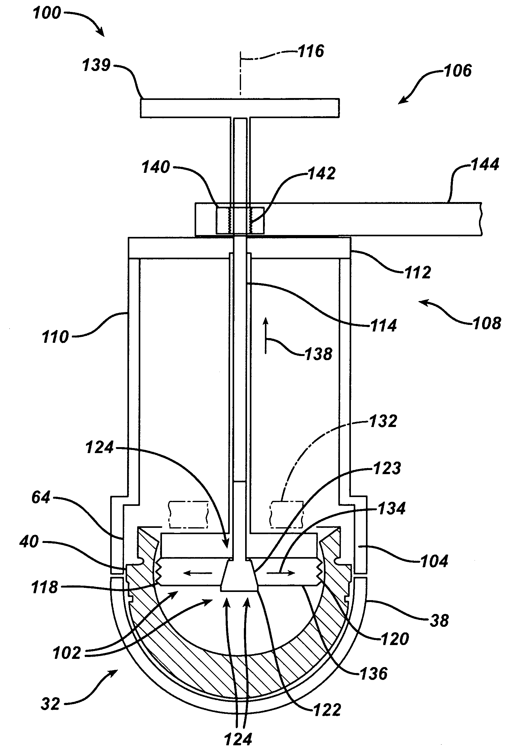
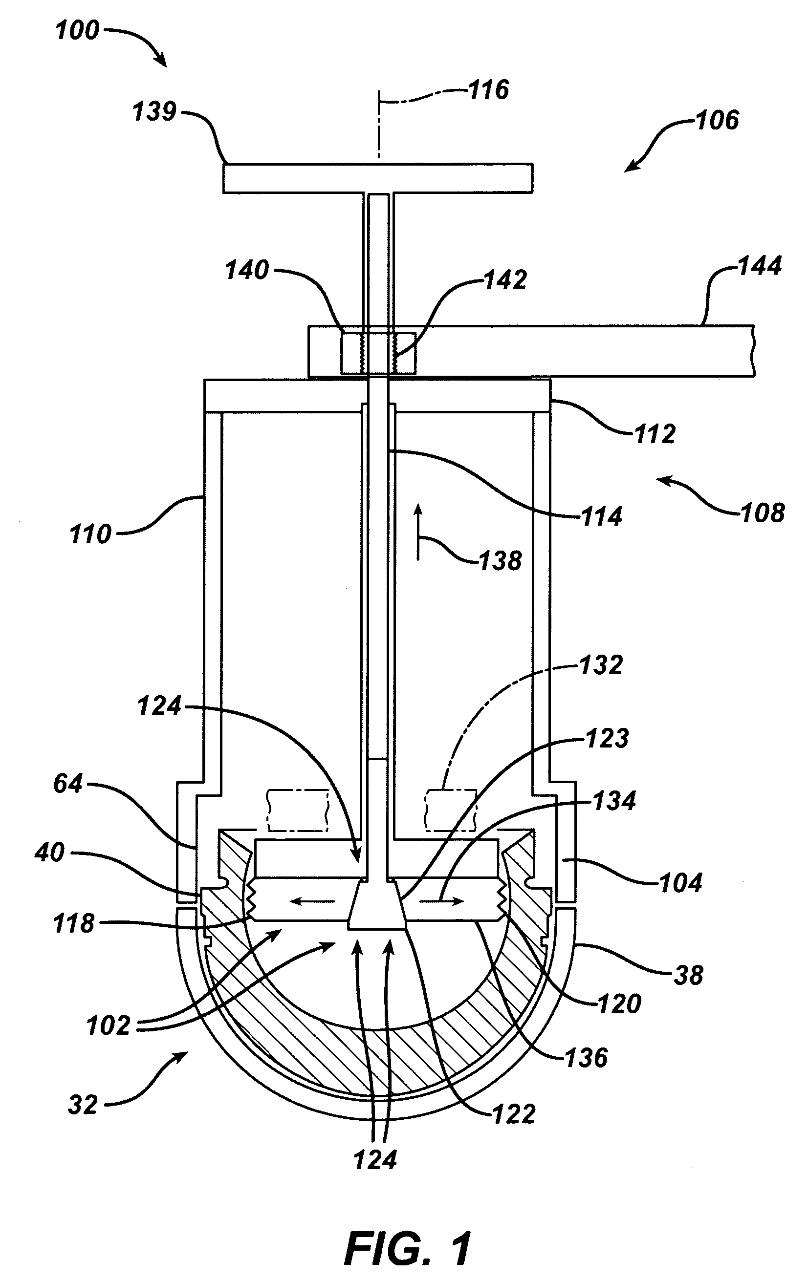
[0093]Referring now to FIG. 5, prosthesis 30 is shown for use with the extraction device of the present invention. The hip prosthesis 30 includes an acetabular cup 32, a head 34, connected to the acetabular cup 32, and a stem 36, fixably attached to the head 34. The acetabular cup 32 is fixably secured to acetabulum 4 while the stem 36 is fixably attached to femur 2.

[0094]The acetabular cup 32 includes a shell 38, which is fixably attached to the acetabulum 4 and a liner 40, which is secured to the shell 38. The shell 38 may be made of any suitable, durable material and may, for example, be made of a metal, a plastic, or a ceramic material. The liner 40 may be made of any suitable, durable material for example, a metal, a plastic, a ceramic. To conform to the ...


PUM


Abstract

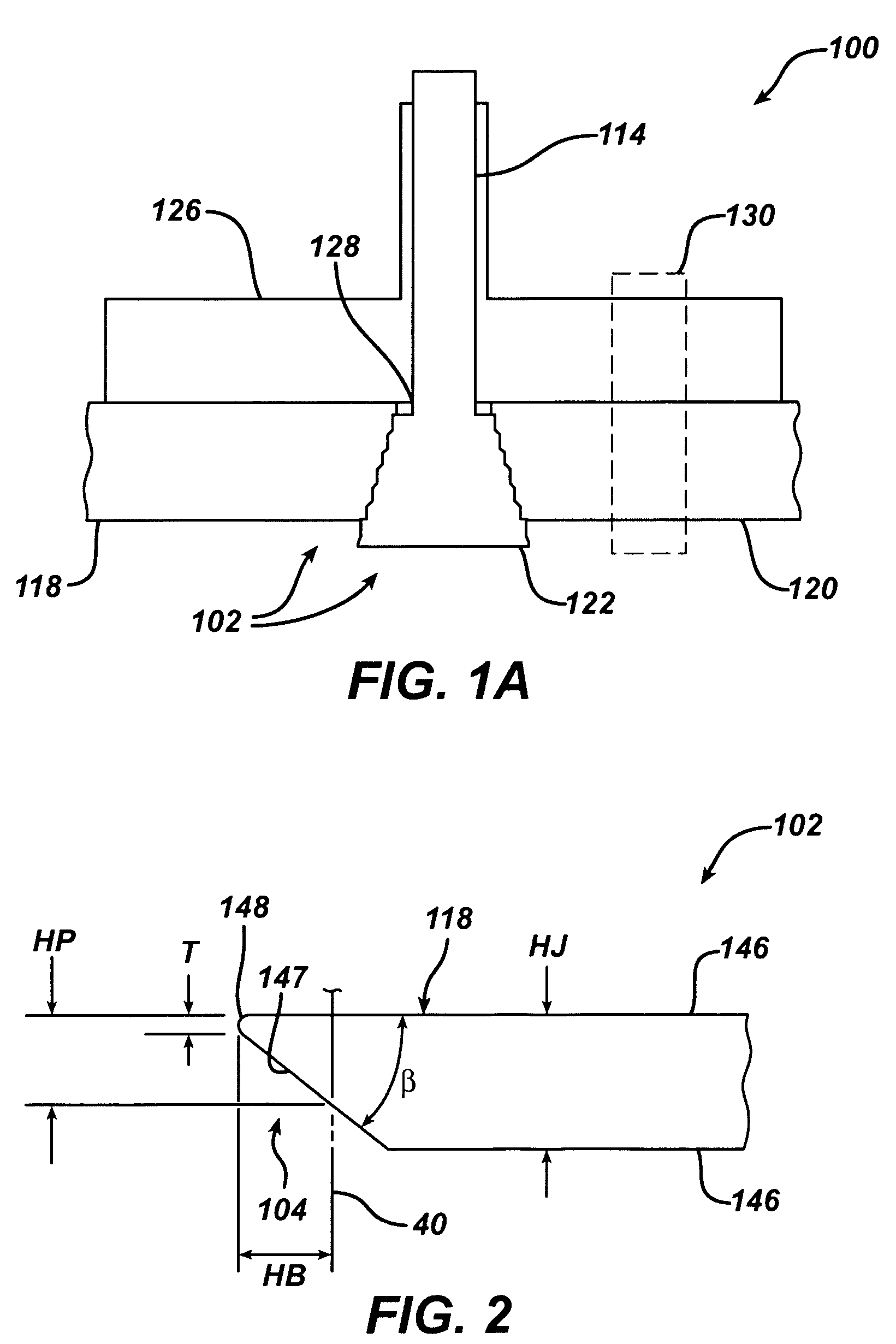
An extraction device for removing a liner from an acetabular cup is provided. The extraction device includes a body and an actuator. The actuator is operably connected to the body. The extraction device also includes a jaw for cooperation with the liner. The jaw includes a portion of the jaw for penetrating into the liner. The jaw is operably connected to the actuator. The actuator is adapted to cooperate with the jaw to provide a first position for the jaw spaced from the liner and a second position for the jaw in contact with the liner.

Description

CROSS-REFERENCE TO RELATED APPLICATIONS[0001]Cross reference is made to the following application: U.S. Pat. No. 7,785,331, titled “ACETABULAR LINER EXTRACTION DEVICE, KIT AND ASSOCIATED METHOD” filed concurrently herewith which is incorporated herein by reference.TECHNICAL FIELD OF THE INVENTION[0002]The present invention relates generally to the field of orthopaedics, and more particularly, to an instrument for use in arthroplasty.BACKGROUND OF THE INVENTION[0003]A joint within the human body forms a juncture between two or more bones or other skeletal parts. The ankle, hip, knee, shoulder, elbow and wrist are just a few examples of the multitude of joints found within the body. As should be apparent from the above list of examples of joints, many of the joints permit relative motion between the bones. For example, the motion of sliding, gliding, and hinge or ball and socket movements may be incorporated into a joint. For example, the ankle permits a hinge movement, the knee allo...

Claims


Application Information

Patent Timeline
Patent Type & Authority Patents(United States)
IPC IPC(8): A61F2/30
CPCA61F2/4637A61F2/34A61F2/32A61F2310/00179A61F2/36A61F2/3662A61F2002/30332A61F2002/30601A61F2002/3069A61F2002/30822A61F2002/3233A61F2002/325A61F2002/3291A61F2002/347A61F2002/3493A61F2002/3611A61F2002/3625A61F2002/365A61F2002/4623A61F2002/4641A61F2002/4642A61F2220/0033A61F2310/00011A61F2/4603A61F2002/30495A61F2002/30594A61F2002/3241
Inventor LEISINGER, STEVEN R.CAYWOOD, JAMES A.
Owner DEPUY PROD INC
Learn More