
DIN rail terminal block

Active Publication Date: 2011-04-12
WUSNG TSAI
View PDF5 Cites 31 Cited by
  • Summary
  • Abstract
  • Description
  • Claims
  • Application Information

AI Technical Summary

Benefits of technology

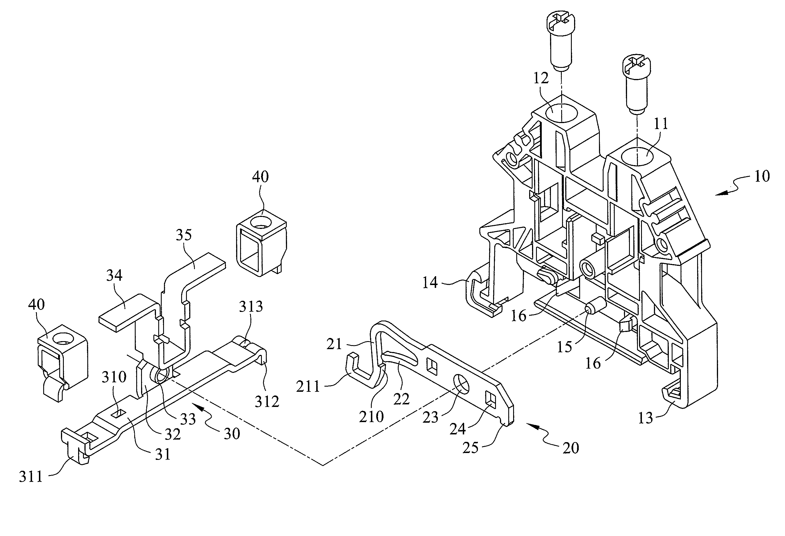
[0007]The primary object of the present invention is to provide a DIN rail terminal block which essentially includes a plastic main body, a resilient metal plate, and a terminal. The resilient plate and the terminal are coupled together by multiple fastening structures and are simultaneously secured in position to the plastic main body, wherein the multiple fastening structures prevent the resilient plate and the terminal from shifting leftward, rightward, upward, or downward with respect to each other. With the terminal configured for ground connection, and the resilient plate for pressing tightly against a DIN rail, the terminal block is stably positioned, provides good electrical connection, and allows easy operation.

Problems solved by technology

However, with such a positioning mechanism, not only are the screw threads of the plastic housing likely to be damaged, but also the surface of the rail tends to be scratched.
In addition, as the screws need to be tightened or loosened during the positioning process, the entire fastening operation can be time consuming.
Moreover, incomplete fastening may result in cases where there are too many wires but too little space.
These are the major drawbacks of the aforesaid conventional DIN rail terminal block.
Nevertheless, as the metal fastener contacts the rail with a curvedly bent portion, the area of contact for electrical connection is rather small, and hence the electrical connection tends to be incomplete.
Besides, the curved surface of the metal fastener is subject to wear and tear, and assembly of the terminal block is laborious.
Furthermore, since the terminal and the metal fastener are supported by engagement between plastic and metal elements in the housing, high-precision molds are required for making the terminal block, which disadvantageously adds to the complexity and costs of manufacture.

Method used


Image

  • DIN rail terminal block
  • DIN rail terminal block
  • DIN rail terminal block

Examples


Embodiment Construction

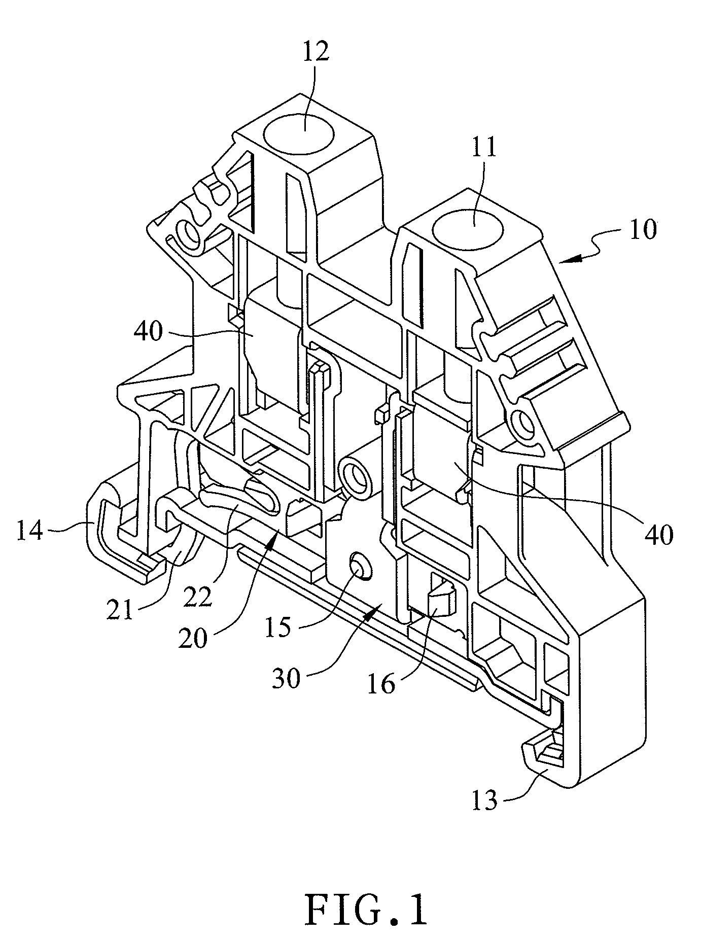
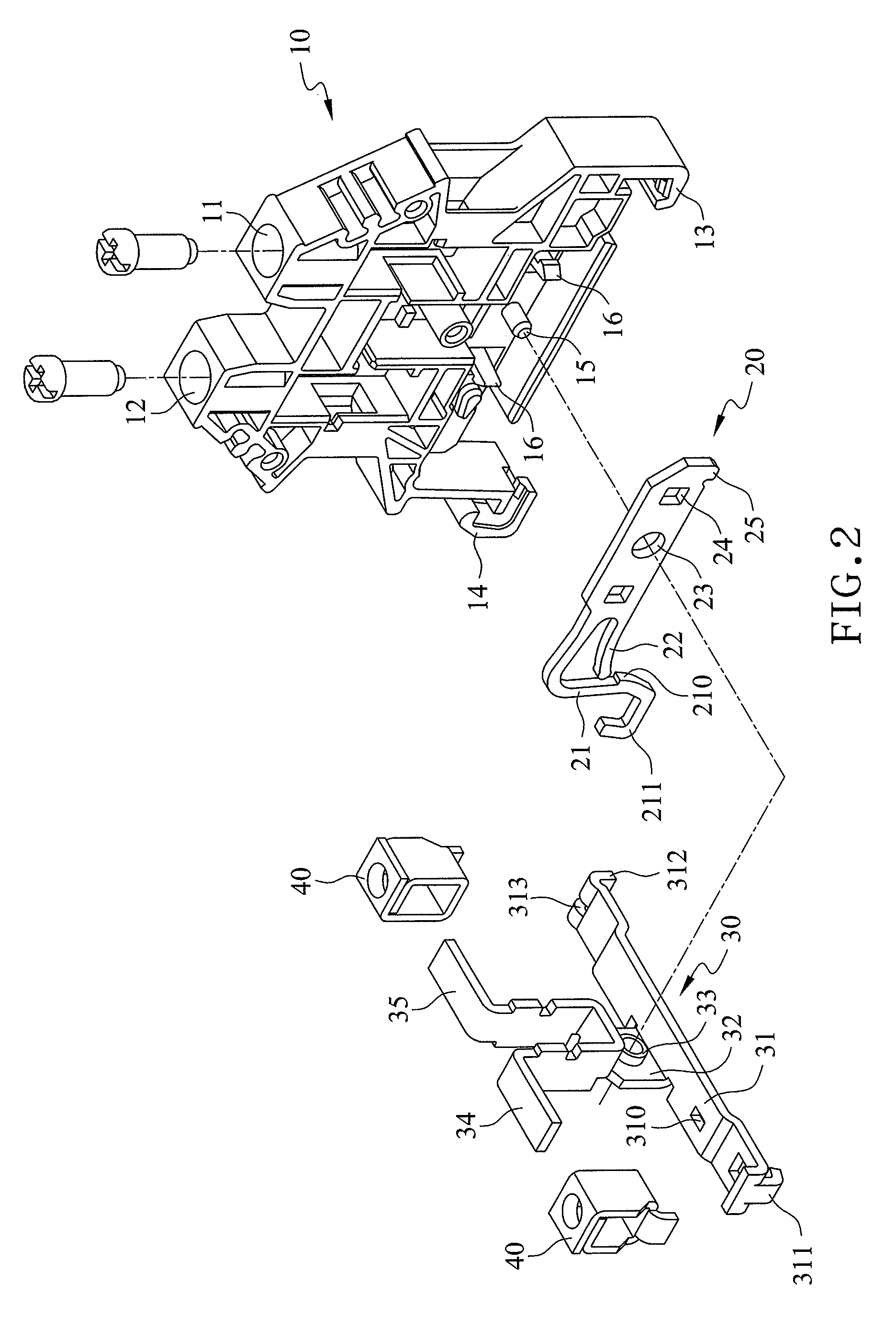
[0018]Referring to FIGS. 1 and 2, a DIN rail terminal block according to an embodiment of the present invention includes a plastic main body 10, a resilient plate 20, and a terminal 30.

[0019]The plastic main body 10 has an end portion provided with two insertion holes 11, 12. The bottom portion of the main body 10 is bilaterally provided with lateral hooks 13, 14. A positioning post 15 and at least one engaging hook 16 are centrally provided in a lower portion of the main body 10. In the present embodiment, there are two engaging hooks 16, which are located on two sides of the positioning post 15, respectively.

[0020]The resilient plate 20 is transversely disposed in the bottom portion of the main body 10 and has one end protrudingly provided with a tenon 25 and the other end provided with a curved fastening arm 21. The fastening arm 21 extends outward to form an L shape and has an end formed with a reinforcing curved portion 211. Besides, a projection 210 is formed on an inner side ...


PUM


Abstract

A DIN rail terminal block essentially includes a plastic main body, a resilient plate, and a terminal. The resilient plate and the terminal are coupled together by multiple fastening structures and are simultaneously secured in position to the plastic main body, wherein the multiple fastening structures prevent the resilient plate and the terminal from shifting leftward, rightward, upward, or downward with respect to each other. With the terminal configured for ground connection, and the resilient plate configured for pressing tightly against a DIN rail, the terminal block is stably positioned, provides good electrical connection, and allows easy operation.

Description

BACKGROUND OF THE INVENTION[0001]1. Technical Field[0002]The present invention relates to a DIN rail terminal block. More particularly, the present invention relates to a terminal block configured to be movably mounted on a DIN rail and including a terminal and a resilient plate that are novel in design and are ingeniously interconnected to enable good electrical connection and secure fastening.[0003]2. Description of Related Art[0004]A DIN rail terminal block is a terminal block movably mounted on a DIN rail and using the DIN rail as an electrode. More specifically, the terminal block is fastened and electrically connected to the DIN rail by a terminal and a resilient plate in the terminal block. As several such terminal blocks of similar functions can be mounted on the same rail to save space and facilitate wiring, DIN rail terminal blocks are in extensive use.[0005]A conventional DIN rail terminal block typically includes a plastic housing and a conductive terminal provided in th...

Claims


Application Information

Patent Timeline
IPC IPC(8): H01R13/66
CPCH01R9/2691
Inventor WU, SHANG TSAI
Owner WUSNG TSAI
Learn More