
LED-based luminaire

a technology of led luminaires and leds, which is applied in the direction of lighting support devices, coupling device connections, light sources, etc., can solve the problems of not having long operating lifetimes, high power requirements of bulbs, and frequent replacement, so as to reduce costs, simplify and standardize led luminaires, and maximize led lighting

Inactive Publication Date: 2011-04-05
DIAMOND CREEK CAPITAL LLC
View PDF123 Cites 69 Cited by
  • Summary
  • Abstract
  • Description
  • Claims
  • Application Information

AI Technical Summary

Benefits of technology

The system enhances the longevity and efficiency of LEDs by effectively managing heat and reducing costs through standardized, customizable designs that optimize power delivery and heat dissipation, leading to improved performance and reduced maintenance.

Problems solved by technology

Incandescent bulbs typically do not have long operating lifetimes and thus require frequent replacement.
Such bulbs also have substantially high power requirements.
Gas-filled tubes, such as fluorescent or neon tubes, may have longer lifetimes, but operate using dangerously high voltages, and may contain toxic materials such as mercury.
By configuring LEDs to fit an arrangement specifically suited to old incandescent technology, such designs typically use such LEDs in a manner that compromises effectiveness and is unduly expensive.

Method used


Image

  • LED-based luminaire
  • LED-based luminaire
  • LED-based luminaire

Examples


embodiment 30

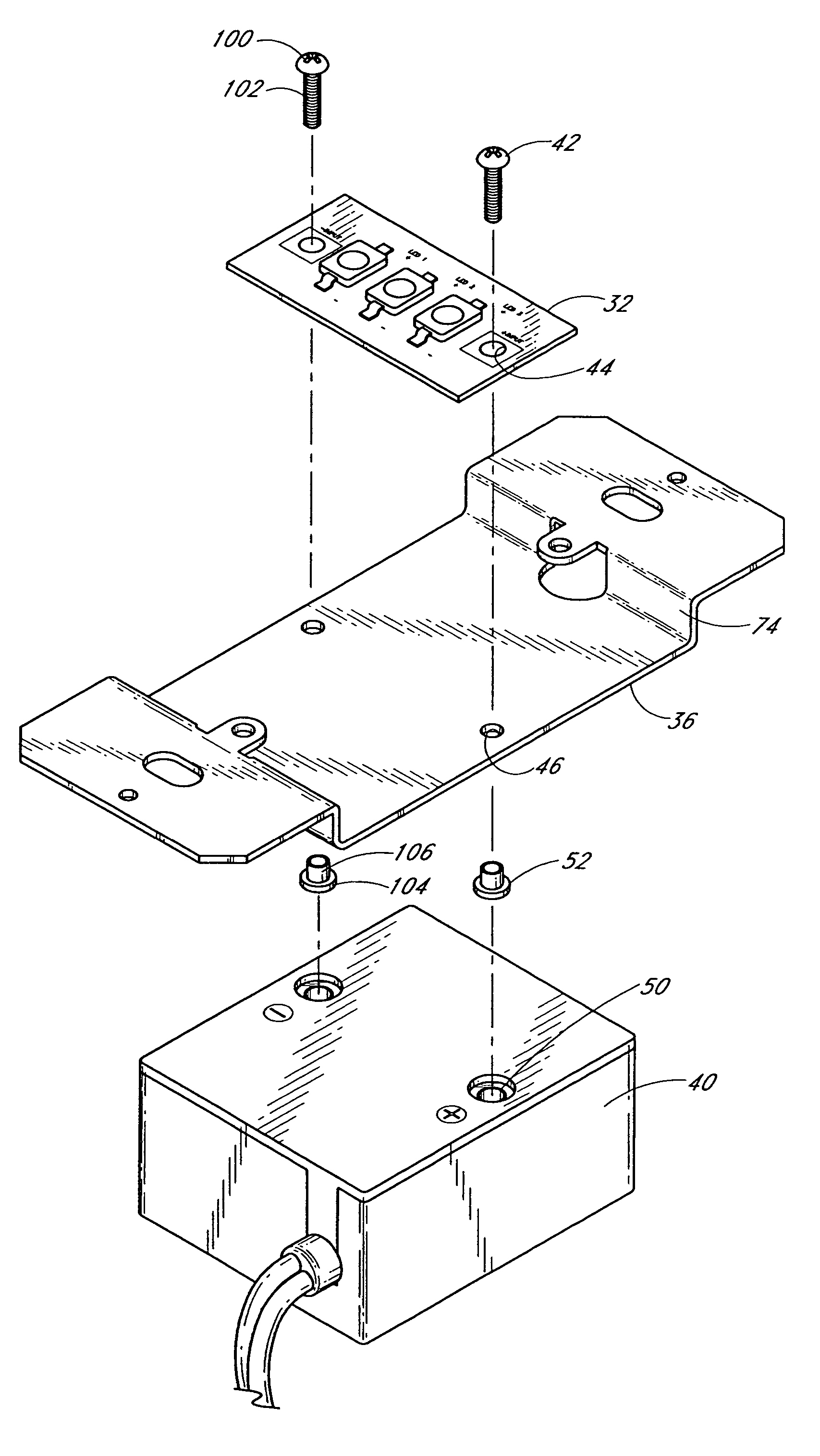
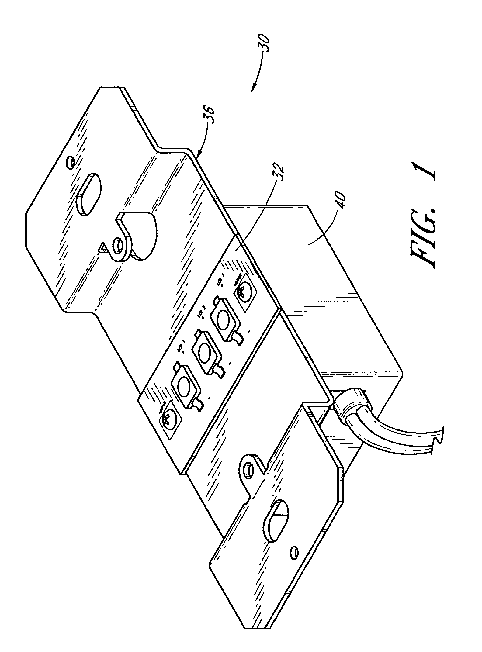
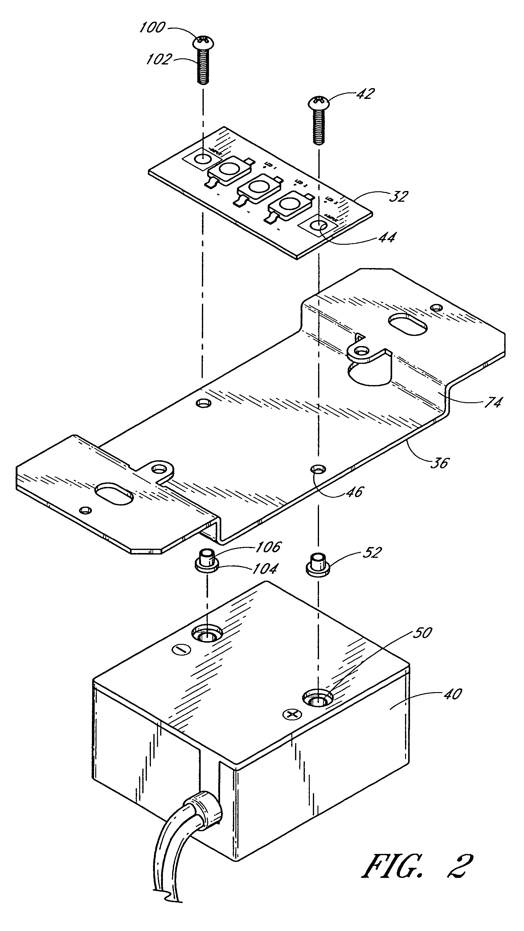
[0047]The rectangular geometry of the illustrated embodiment is especially suitable for the illustrated luminaire embodiment 30 discussed herein. It is to be understood, however, that other embodiments may benefit from differing module configurations. For example, it is contemplated that modules may be square, circular, oval, irregularly-shaped or may have widely varying rectangular dimensions (such as being especially long and thin). Additionally, although the illustrated modules are relatively flat, it is understood that other embodiments may include modules having simple or complex three dimensional shapes.

[0048]With continued reference to FIG. 3, the body 54 of the lighting module 32 can be made of various materials, rigid or flexible. However, most preferably, the body comprises a generally rigid heat conductive material such as aluminum. Preferably, the body 54 is constructed of a material having high heat conductance properties such as a heat conductivity greater than about 7...

embodiment 130

[0069]FIG. 7 presents an exploded view of the embodiment illustrated in FIG. 6 but not showing the back housing. As shown, the illustrated embodiment 130 employs three LED-based lighting modules 32A-C that are configured to fit in a module mounting portion 142 of the mount base 136. The module mounting portion 142 is specifically configured to accommodate all three modules 32A-C. As shown, the module mounting portion 142 of the base 136 is offset from a front surface 143 of the base so that the lighting modules are offset inwardly relative to the front surface 143. Additionally, the mounting portion 142 is shaped so as to complement the shape of the lighting modules 32A-C. In the illustrated embodiment, the module mounting portion 142 is substantially rectangular and flat-surfaced so as to complementarily accommodate the lighting modules. Module apertures 44 are formed through each lighting module 32, and three pairs of mounting base apertures 146A-C are formed through the mounting ...


PUM


Abstract

An LED-based luminaire includes a driver configured to convert line voltage into a desired power configuration. Elongate fasteners attach one or more LED-based lighting modules to a mount member and also to energized poles of the power driver. The fasteners communicate electrical energy from the power driver to the lighting module. In one embodiment, the mount member functions as a heat sink, and it includes a bumpy surface coating having a texture with sufficient feature heights to enhance heat transfer between the heat sink and the surrounding environment.

Description

RELATED APPLICATIONS[0001]This application is based upon and claims the benefit of U.S. Application Ser. No. 60 / 681,072, which was filed on May 13, 2005, the entirety of which is hereby incorporated by reference.BACKGROUND OF THE INVENTION[0002]1. Field of the Invention[0003]The present invention relates generally to light emitting diode (LEDs) based lighting devices, and more particularly to configurations for LED-based luminaires and for managing heat generated by LEDs in such luminaires.[0004]2. Description of the Related Art[0005]Conventional lighting applications typically employ incandescent or gas-filled bulbs. Incandescent bulbs typically do not have long operating lifetimes and thus require frequent replacement. Such bulbs also have substantially high power requirements. Gas-filled tubes, such as fluorescent or neon tubes, may have longer lifetimes, but operate using dangerously high voltages, and may contain toxic materials such as mercury.[0006]In contrast, light emitting...

Claims


Application Information

Patent Timeline
Patent Type & Authority Patents(United States)
IPC IPC(8): F21V15/00
CPCF21V19/0055F21V23/02F21V29/773F21V29/75F21V29/004F21K9/00F21Y2101/02Y10S362/80F21Y2103/10F21Y2105/16F21Y2115/10F21V29/89
Inventor LYNCH, MANUEL
Owner DIAMOND CREEK CAPITAL LLC
Learn More