
Battery management system with runtime reserve analysis

a technology of runtime reserve and battery management system, which is applied in the field of large stationary battery management, can solve the problems of large discrepancy between design life and actual life, difficulty in managing storage devices, and difficulty in ensuring uninterrupted power servi

Active Publication Date: 2011-03-29
ASKALITY LLC
View PDF33 Cites 14 Cited by
  • Summary
  • Abstract
  • Description
  • Claims
  • Application Information

AI Technical Summary

Benefits of technology

"The present system is a system for managing a group of batteries. It includes a battery unit with a unique identifier, software for inputting data on the battery unit, a communication interface for connecting to a computer network, and a database for storing battery-related data. The system uses the unique identifier to track each battery unit and collect data on it, such as an ohmic test value and a baseline ohmic value. The software system then generates a runtime reserve report based on this data. Overall, the system allows for better management of batteries and ensures optimal performance."

Problems solved by technology

The discrepancy between design life and actual life is a major problem for users of these batteries.
Predicting their useful lifespan to help manage servicing schedules, replacement cost and budgeting for uninterrupted power service is an important and complex task.
This electrical combination of batteries compounds the difficulty of managing these storage devices.
In sum, managing stationary batteries is difficult, and is generally not a core competency of most businesses that use these batteries.
Upon testing, gross failure of the batteries is apparent, as would be an impending failure within a short time horizon, such as a week or two.
These short-term indicia of impending battery failure do not allow planning and budgeting to replace critical power assets.
In many cases, even where the batteries are in good condition there may be a deficiency of backup power due to changes in load requirements.
Prior methods of predicting battery failure are limited to predicting an imminent failure by monitoring a battery jar.
Again, such a short horizon of impending battery failure does not allow planning and budgeting to replace critical power assets.

Method used


Image

  • Battery management system with runtime reserve analysis
  • Battery management system with runtime reserve analysis
  • Battery management system with runtime reserve analysis

Examples


Embodiment Construction

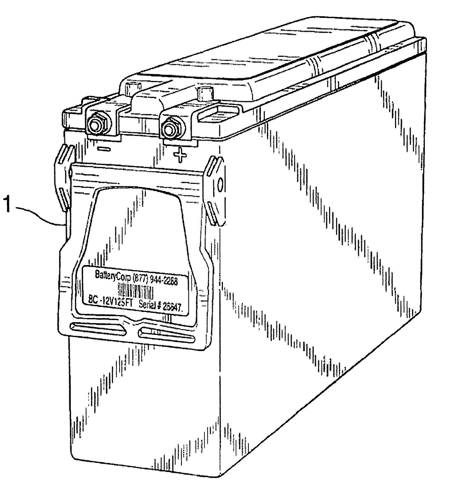
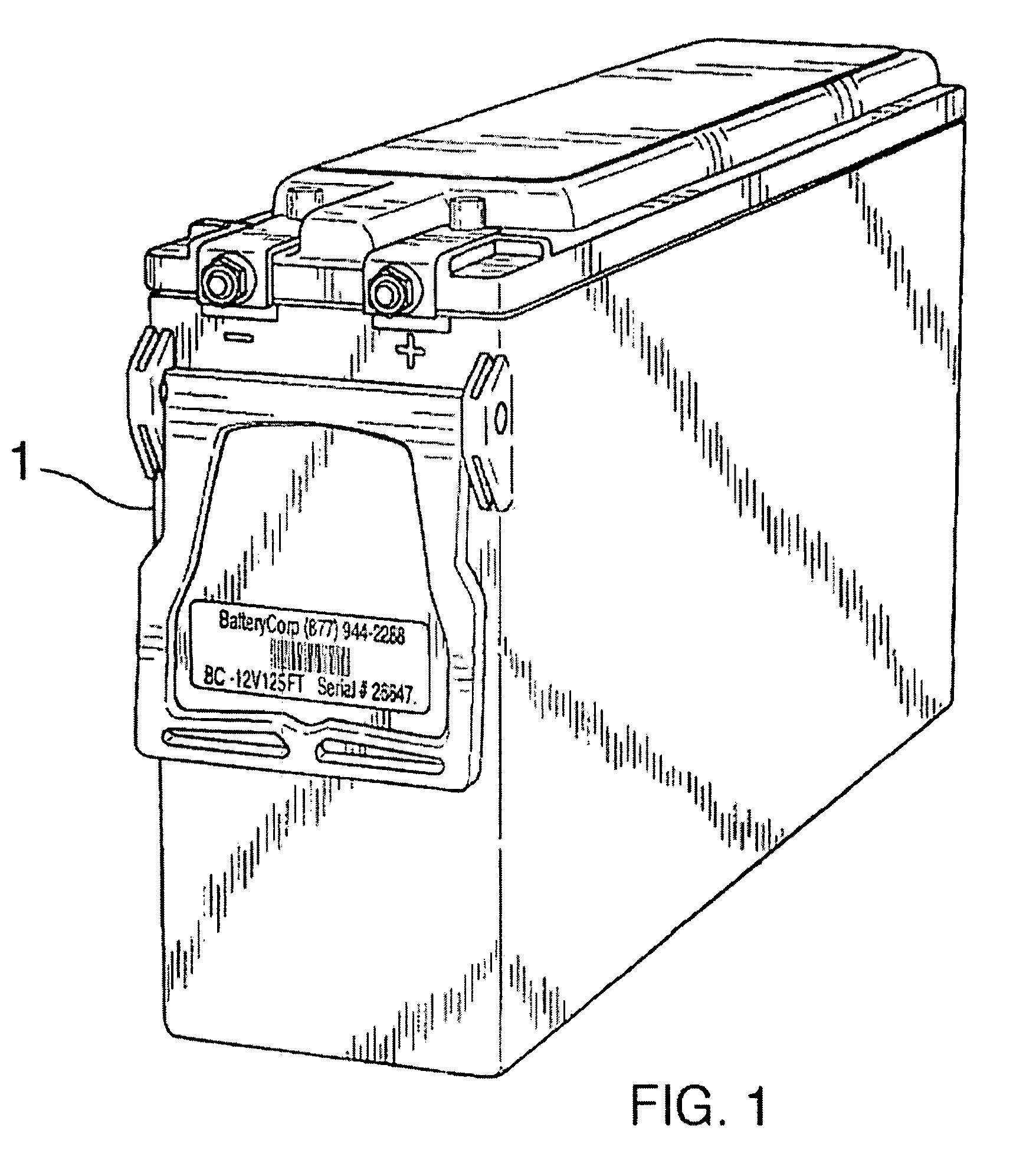
[0017]The invention improves way battery systems are managed. Battery management generally comprises a set of tasks. Some of those tasks include testing, maintenance, installation, fulfillment and disposal. The invention is capable of performing these tasks even over a wide geographical area. The main components include a battery or series of batteries; a testing device; and a reporting platform.

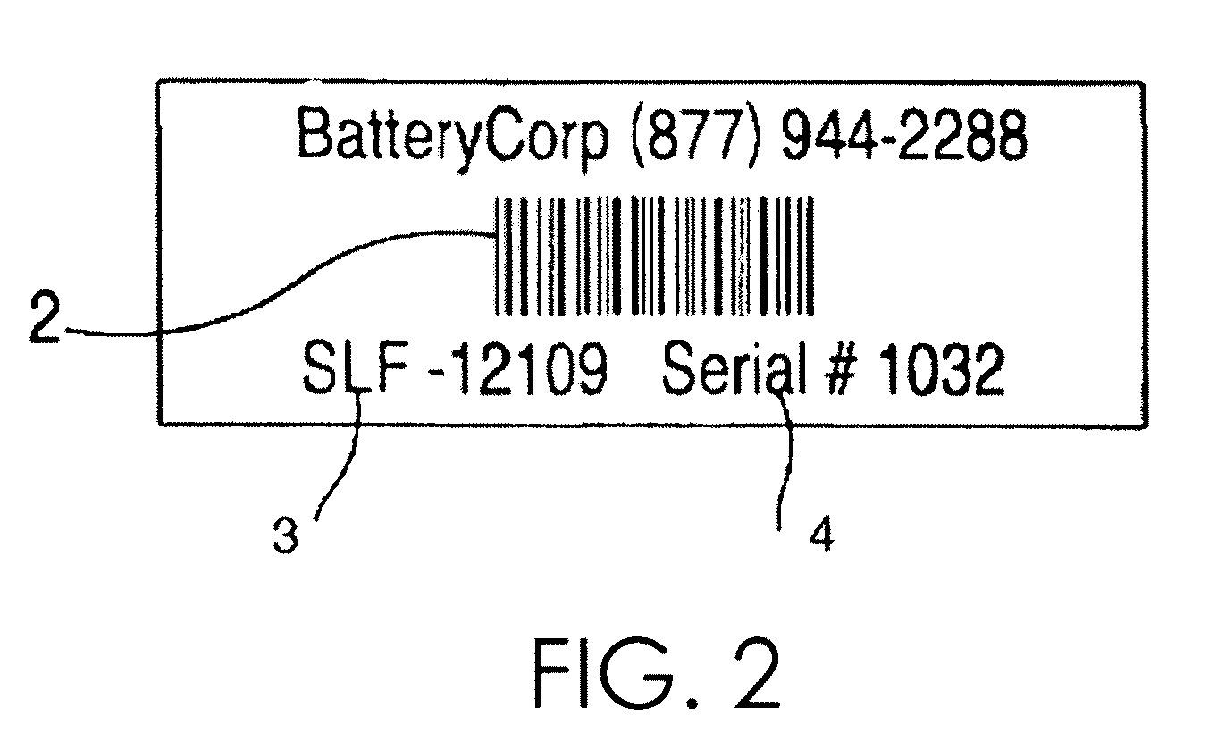
[0018]In accordance with the purposes of the invention, the battery or series of batteries may be lead-acid having a unique identifier and equipped with technology to enable automated tracking and runtime analysis. A unique identifier may be embodied as a bar coded label, or a virtual identifier (usually a series of alpha-numeric characters). The unique identifier is associated with attributes of the battery. Preferably, the attributes associated with the unique identifier include an ohmic test value and other power properties, such as voltage, maximum charge, and life. The unique identifier...


PUM

PropertyMeasurementUnit
physicalaaaaaaaaaa
impedanceaaaaaaaaaa
conductanceaaaaaaaaaa

Abstract

The invention relates to the management of large stationary batteries. The invention is a comprehensive system and process for the management of stationary batteries that are used for backup power and are deployed in widely dispersed locations. The system may be comprised of a plurality of batteries and web-based software. The system software can automatically analyze, determine and report the number of batteries and total cost based on required runtime reserve by computing the power of batteries currently in a system and available batteries for installation.

Description

CROSS REFERENCE TO RELATED APPLICATIONS[0001]This application is a continuation-in-part of, and claims priority to U.S. application Ser. No. 11 / 491,807, filed Jul. 24, 2006, now abandoned related to Ser. No. 11 / 125,450, filed May 10, 2005, now U.S. Pat. No. 7,616,002 related to U.S. application Ser. No. 11 / 125,631, filed May 10, 2005, now U.S. Pat. No. 7,349,816 related to U.S. application Ser. No. 11 / 025,816, filed Dec. 29, 2004, now U.S. Pat. No. 7,317,995 related to U.S. application Ser. No. 11 / 025,305, filed Dec. 29, 2004 (now U.S. Pat. No. 7,206,704, issued Apr. 17, 2007), each of the foregoing applications being continuations-in-part of U.S. application Ser. No. 10 / 749,004, filed Dec. 30, 2003 (now U.S. Pat. No. 7,003,431, issued Feb. 21, 2006), and all of the foregoing being incorporated herein by reference in their entirety.BACKGROUND OF THE INVENTION[0002]The invention relates to the management of large stationary batteries, and incorporates a method of predictive battery f...

Claims


Application Information

Patent Timeline
Patent Type & Authority Patents(United States)
IPC IPC(8): H02J7/00G01N27/416G01R31/36
CPCG06Q10/087H01M10/06H01M10/42H01M10/4207H01M10/48G01R31/3679H01M10/4221Y02E60/126G01R31/392Y02E60/10
Inventor QUINT, JONATHAN B.DWORKIN, STEVEN H.
Owner ASKALITY LLC
Learn More