Measurement control method of an injection molding machine

a technology of injection molding machine and measurement control method, which is applied in the direction of fluid pressure measurement, manufacturing tools, instruments, etc., can solve the problems of limited extent to which injection molding efficiency and mass productivity can be raised, difficult to achieve securing responsiveness and stability, and significant amount, so as to achieve secure a high degree of measurement precision, and accurately and reliably stop both screw rotations

Active Publication Date: 2011-03-29
NISSEI PLASTIC IND CO LTD
View PDF12 Cites 3 Cited by
  • Summary
  • Abstract
  • Description
  • Claims
  • Application Information

AI Technical Summary

Benefits of technology

[0010]The objective of the present invention is to provide a measurement control method of an injection molding machine that secures a high degree of measurement precision by accurately and reliably stopping both the screw rotation and retraction in a set measurement ending position, and especially to provide a measurement control method of an injection molding machine that is sufficiently suited to the formation of, for instance, a thin optical disk which recently especially requires a high degree of measurement precision.
[0011]A further objective of the present invention is to provide a measurement control method of an injection molding machine in which the control precision of the measurement ending position can be raised while the cycle time can shortened thereby maintaining high injection molding quality and improving injection molding efficiency and mass productivity further enabling high speed injection molding to be realized.
[0012]A further objective of the present invention is to provide a measurement control method of an injection molding machine that devises accuracy and simplicity in position control for the measurement ending position while enabling reliable and accurate back pressure control to be realized in a minimal length area by raising the responsiveness and stability of the control.

Problems solved by technology

First, as described in aforementioned Publication No. 6 (1994)-61800, when adopting a control method that detects the screw position and the screw retraction rate and calculates the number of screw rotations to stop the screw by a measurement ending position while making the calculated number of screw rotations to be a rotation drive command, a significant amount of time is required until a screw arrives at the measurement ending position as the rotation rate of a screw near to the measurement ending position approaches zero without limit. Since shortening the cycle time to something that is beneficial to raising the control precision of the screw position cannot be devised, a limitation occurs in the extent to which injection molding efficiency and mass productivity can be raised while being extremely inconvenient relative to realizing high speed injection molding.
Therefore, it is difficult to achieve securing responsiveness and stability in something that is beneficial to raising control precision of the screw position and allows back pressure control in a minimal length area while back control requires adjustments in the screw rotation rate as well as inviting complications to control.
Further, although measurement control is required to secure a high degree of measurement precision in reliably stopping both the screw rotation and retraction at a measurement ending position (measurement ending position), in neither case is consideration given to reliably stopping both the screw rotation and retraction, and nor do they especially provide sufficient measures for the formation of, for instance, a thin optical disk recently requiring a high degree of measurement precision.

Method used


Image

  • Measurement control method of an injection molding machine
  • Measurement control method of an injection molding machine
  • Measurement control method of an injection molding machine

Examples


Embodiment Construction

[0031]A detailed description is given hereafter by using preferred embodiments that relate to the present invention with reference to drawings. In addition, the attached drawings are not for specifying the present invention, but which are for making it easier to understand the present invention. Further, in order to avoid any obscuring, a detailed description is omitted regarding the areas which are common knowledge.

[0032]First, the construction of an injection molding machine M that has the ability to implement a measurement control method that relates to the present embodiment is described with reference to the FIG. 3 and FIG. 4.

[0033]The injection molding machine M shown in FIG. 3 shows only the injection device Mi in which a mold clamping device is excluded. The injection device Mi comprises intermediate injection platform 11 and a driving platform 12, and the back end of a heating cylinder 13 is supported by the front surface of the injection platform 11. The heating cylinder 1...


PUM

PropertyMeasurementUnit
lengthaaaaaaaaaa
timeaaaaaaaaaa
massaaaaaaaaaa

Abstract

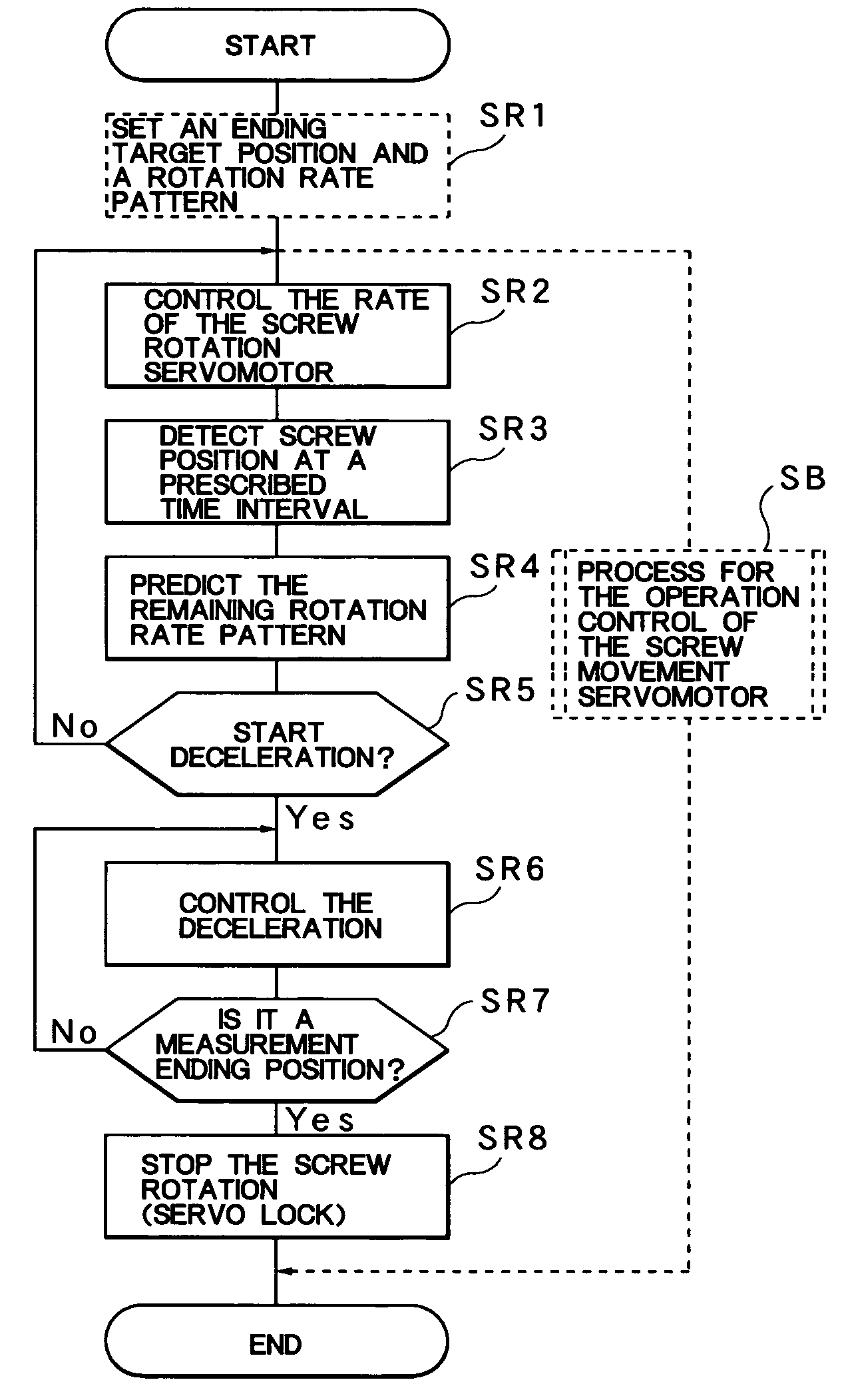
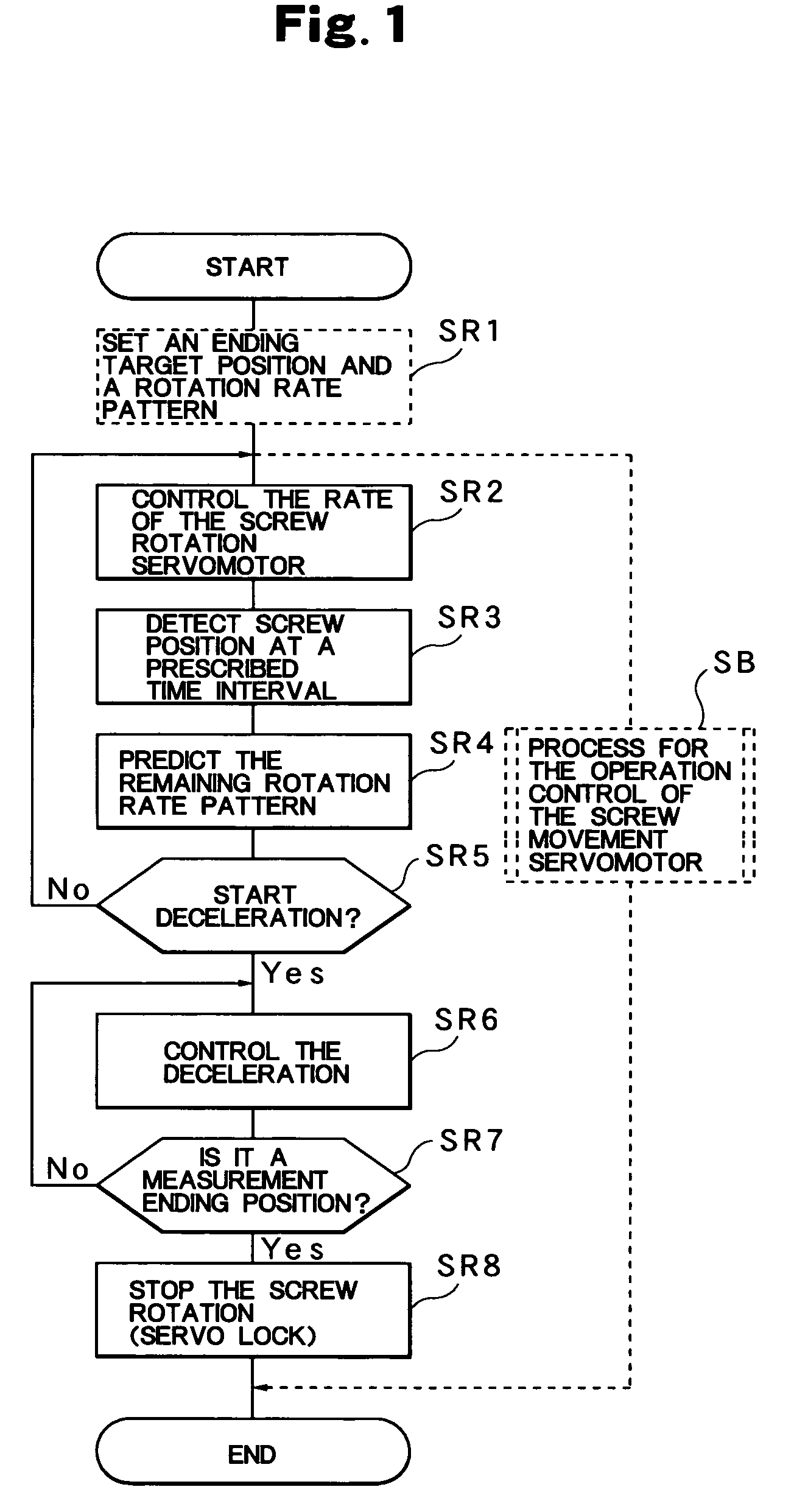
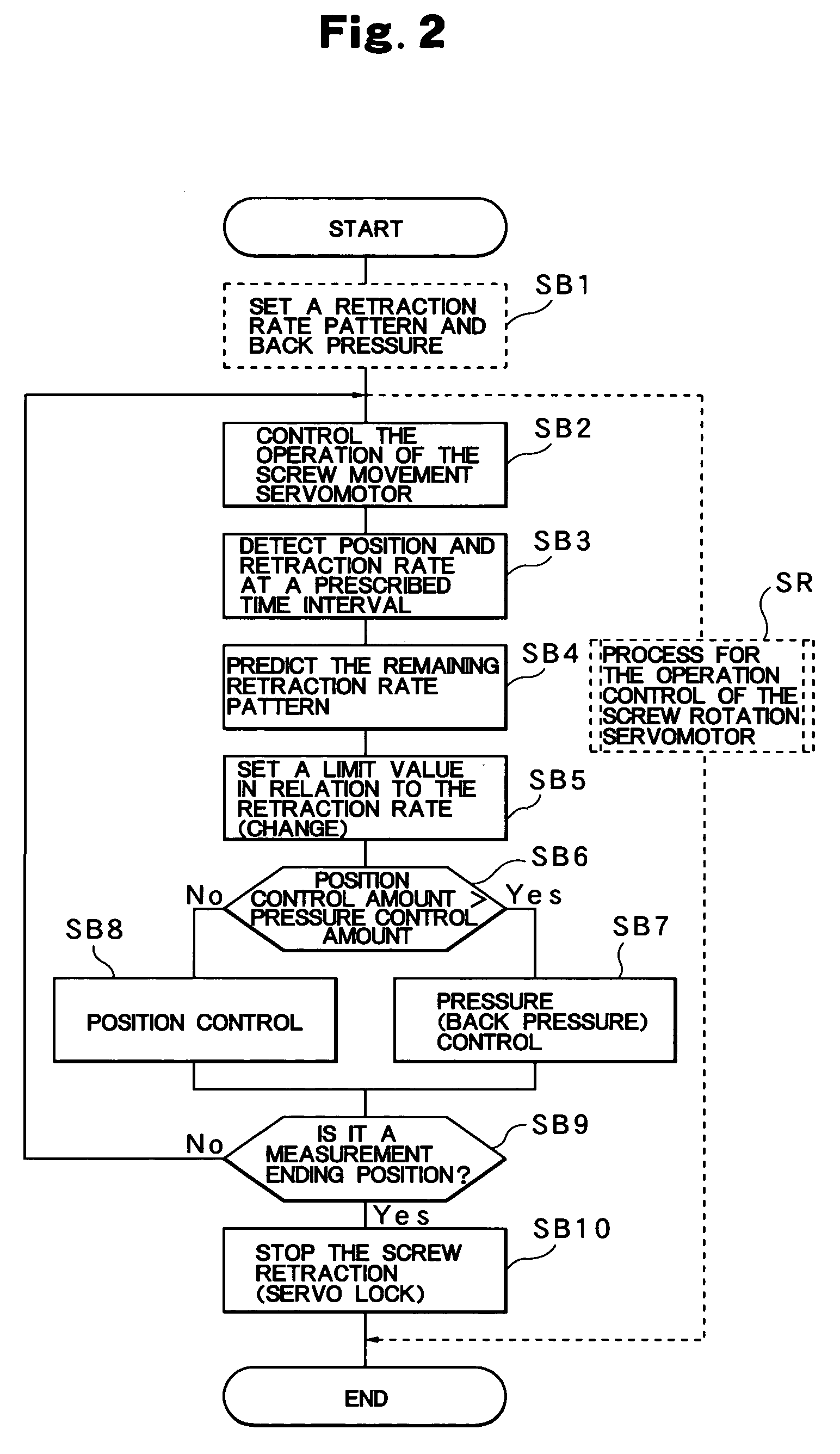
A measurement control method uses an ending target position Xes calculated by adding a prescribed length Ls to a measurement ending position Xe. A rotation rate pattern Ar for rotating a screw 2, a back pressure Ps in relation to the screw 2, and a retraction rate pattern Ab for the screw 2 to retract, are set in advance. The remaining rotation rate pattern Ar to stop the rotation of the screw 2 at the ending target position Xes from the detected screw position X, is calculated at the time of measurement, and the rotation of the screw 2 is stopped based on the calculation. Further, the remaining retraction rate pattern Ab is calculated from the detected retraction rate Vd, and the retraction of the screw 2 is stopped based on the calculation. The result is the stopping of the screw at the measurement ending position Xe.

Description

BACKGROUND OF THE INVENTION[0001]1. Field of the Invention[0002]The present invention relates to a measurement control method of an injection molding machine that performs a measurement by screw rotation and ends the measurement when the screw retracts to a preset measurement ending position.[0003]2. Description of the Relevant Art[0004]In general, an injection cycle of an injection molding machine has a measurement process and an injection process; and during the measurement process, measurement is performed by rotating a screw while measurement control is performed in which measurement is ended when a screw is retracted to a preset measurement ending position. However, although various types of measurements are taken during the measurement process such as rate control, pressure control, and position control, increasing the control precision for a series of controls in the measurement process is extremely important for securing consistent injection molding quality and obtaining an ...

Claims


Application Information

Patent Timeline
Patent Type & Authority Patents(United States)
IPC IPC(8): B29C45/76
CPCB29C45/76B29C2945/76083B29C2945/76187B29C2945/76367B29C2945/76575B29C2945/76608B29C2945/76665B29C2945/76846
Inventor SHIOZAWA, FUMIOIKEDA, TETSUOHAKODA, TAKASHIYODA, HIDENOBU
Owner NISSEI PLASTIC IND CO LTD
Why Eureka
Try Eureka