
Optical recording medium

a recording medium and optical technology, applied in the field of optical recording mediums, can solve the problems of inability to obtain sufficient recording characteristics, inability to meet the requirements of recording/reading light, and inability to achieve satisfactory recording characteristics, etc., to achieve satisfactory storage stability, reduce the stress caused by recording/reading light, and high quality

Inactive Publication Date: 2011-03-22
CMC MAGNETICS CORPORATION +1
View PDF25 Cites 4 Cited by
  • Summary
  • Abstract
  • Description
  • Claims
  • Application Information

AI Technical Summary

Benefits of technology

[0025]In the invention, the first reflective layer preferably comprises silver as a main component because the remarkable effect of the invention is apt to be obtained. Namely, when the invention is applied to the case where the first reflective layer comprises silver as a main component, then not only the durability (reduced deterioration in high-temperature high-humidity durability test) of high-density or high-speed recording parts can be secured while using silver or a silver alloy, which has a low cost, but also problems such as an adhesive-layer deterioration by a photocatalytic reaction attributable to silver and a corrosion of the reflective layer due to the deteriorated adhesive can be improved.
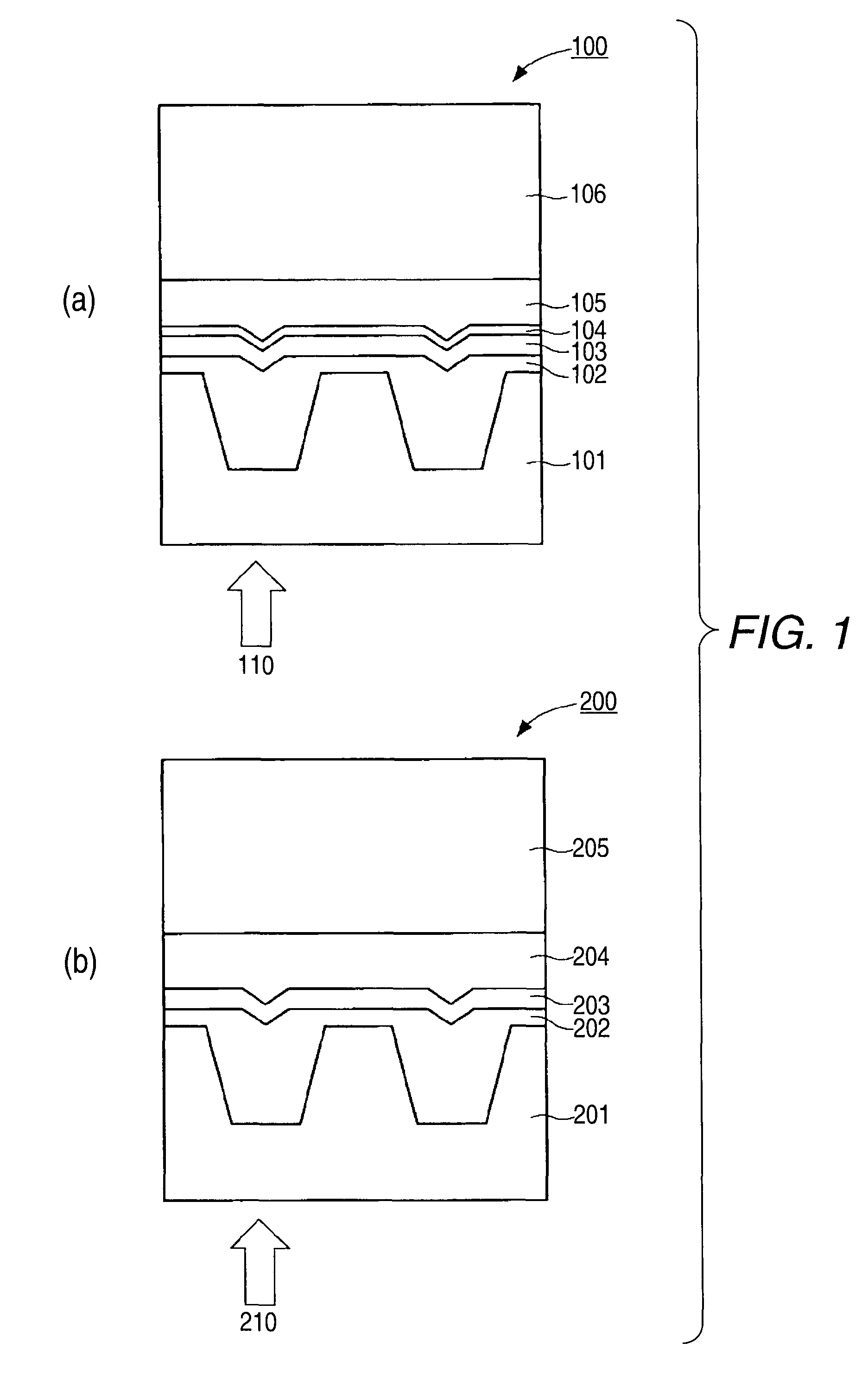
[0026]It is preferred in the invention that the film thickness of the first reflective layer should be in the range of from 50 nm to 200 nm and the film thickness of the second reflective layer be in the range of from 0.5 nm to 60 nm. This is because by regulating the film thicknesses of the layers so as to be within those ranges, a sufficient reflectance and a sufficient radiating effect are secured and the stresses to be caused by a recording / reading light can be reduced.
[0027]In the invention, the recording layer preferably has a recording mark in which a minimum mark length is 0.4 μm or smaller. This is because the effect of the invention is more remarkable in such high-density recording, i.e., in an optical recording medium in which recording parts are irradiated with a higher recording power light than before and are exposed to a higher temperature than before.
[0028]In the invention, the optical recording medium preferably is capable of recording at a recording linear speed of 28 m / s or higher. This is because the effect of the invention is remarkable in an optical recording medium which comprises an organic dye and in which high-speed recording is conducted. The reason for this is the same as that for the optical recording medium having the recording mark in which a minimum mark length is 0.4 μm or smaller.Advantage of the Invention
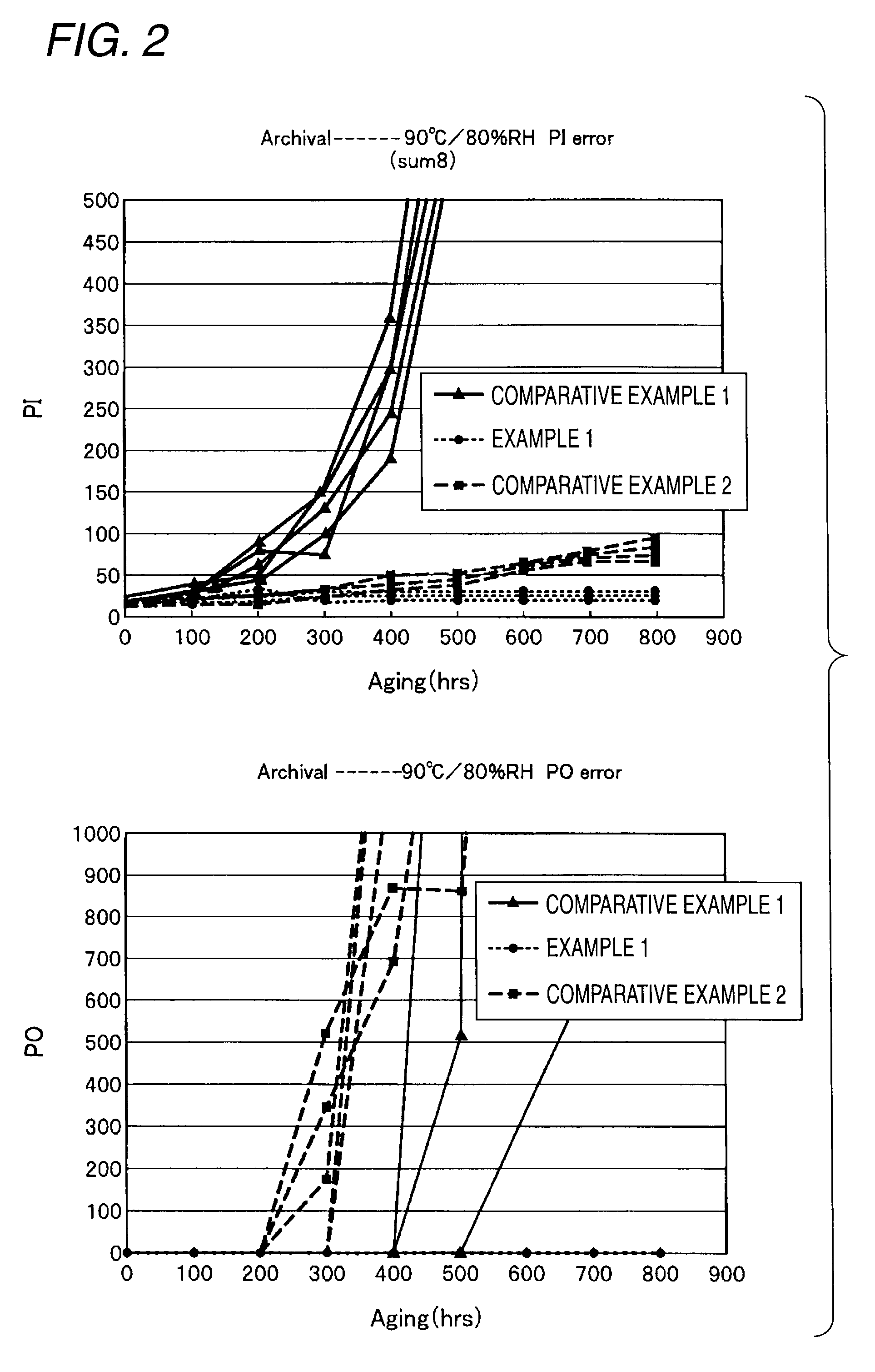
[0029]According to the invention, a recordable optical recording medium for an archival application is hence obtained which has high quality and satisfactory storage stability when used in an application of high-density high-speed recording.

Problems solved by technology

These optical recording media comprising a recording layer comprising an organic dye are known to increase in error due to the influence of water present at the interface between the organic-dye layer and the reflective layer (see patent document 1).
There has hence been a possibility that optical recording media such as those described in patent document 1 and patent document 2 cannot have satisfactory recording characteristics when used under the recording condition originally possessed in the optical recording apparatus and optimized for the optical recording media employing a silver reflective layer.
Furthermore, since the reflective layer of those optical recording media has a lower reflectance than the silver reflective layer due to the constitutions thereof, there has been a possibility that sufficient recording characteristics cannot be obtained or the choice of a recording material might be narrowed.
However, this necessitates a reduction in the film thickness of the dye recording layer, resulting in a decrease in reflectance.
There has hence been a possibility that it might be difficult to maintain recording characteristics.
In this case, however, the first reflective layer has a film thickness reduced to 50 nm or smaller in order to enhance the effect produced by the thermal conductivity of the second reflective layer, and there is hence a problem that a decrease in reflectance in some degree is unavoidable.
Furthermore, in view of the current situation in which optical recording apparatus optimized for an optical disk employing a silver reflective layer have already spread, there has been a possibility that optical recording media having that constitution cannot have satisfactory characteristics under the recording condition originally possessed in the optical recording apparatus because these recording media require different recording characteristics.
However, there has been a possibility that the optical recording medium employing a gold reflective layer cannot have satisfactory recording characteristics when used with the optical recording apparatus which have already spread, as stated above.
In addition, since gold has a poor affinity for an organic-dye recording layer, there has been a possibility that interfacial separation between the reflective layer and the recording layer might occur to cause errors.

Method used


Image

  • Optical recording medium
  • Optical recording medium
  • Optical recording medium

Examples


example 1

Preparation of Optical Recording Medium

[0128]First, a polycarbonate was injection-molded with a nickel stamper having a groove formed in the surface thereof to thereby form a resin substrate which had a diameter of 120 mm and a film thickness of 0.60 mm and had a groove having a pitch of 0.74 μm, width of 320±50 nm, and depth of 150±25 nm. A tetrafluoropropanol solution (concentration, 1.5% by weight) of a mixture of dye A and dye B (dye A / dye B=60% by weight / 40% by weight) which were metal-containing azo dyes respectively represented by the following chemical formulae, as an organic dye compound, was prepared. This was dropped onto the resin substrate and subjected to spin coating.

[0129]Thereafter, the coating film was dried at 70° C. for 30 minutes to form a recording layer. In the groove part of the resin substrate, the recording layer had a film thickness of about 80 nm and a value of OD (optical density) as measured at a wavelength of about 595 nm with ETA-RT, manufactured by E...

examples 2 to 5

[0152]Laminated disks were produced in completely the same manner as in Example 1, except that the film thicknesses of the first reflective layer which was made of pure silver, and the second reflective layer which was made of pure gold, were changed as shown in Table 3.

[0153]The disks of Examples 2 to 5 and the disks of Example 1 and Comparative Examples 1 to 6 were subjected to the same recording as in Example 1 and then examined for reflectance and jitter. The values of reflectance (average for disk samples) and jitter value (average for disk samples) for these disks are shown in Table 3. These measured values were obtained by examining the disks before the durability test.

[0154]

TABLE 3Reflectance, Jitter Value (average for disks)Example 1Example 2Example 3Example 4Example 5First reflectivepurepurepurepurepurelayersilversilversilversilversilver100 nm120 nm140 nm140 nm140 nmSecond reflectivepure goldpure goldpure goldpure goldpure goldlayer 50 nm 50 nm 50 nm 30 nm 20 nmTotal refle...

example 6

Preparation of Optical Recording Medium

[0159]First, a polycarbonate was injection-molded with a nickel stamper for CD-R production which had a groove formed in the surface thereof to thereby form a resin substrate which had a diameter of 120 mm and a thickness of 1.2 mm and had a groove having a pitch of 1.5 μm. A solution prepared by dissolving a phthalocyanine-based dye as an organic dye compound in an organic solvent was dropped onto the resin substrate and subjected to spin coating. Thereafter, the coating film was dried with heating to form a recording layer. The film thickness of the recording layer was regulated so that the recording layer had an OD value of 0.57 as measured at the maximum absorption wavelength for the dye compound.

[0160]As soon as possible after the formation of the recording layer, a sputtering film of pure silver was deposited in a film thickness of 80 nm as a first reflective layer on the recording layer. Furthermore, a sputtering film of pure gold was de...


PUM

PropertyMeasurementUnit
lengthaaaaaaaaaa
mark lengthaaaaaaaaaa
wavelengthaaaaaaaaaa

Abstract

The invention is principally to provide an archival optical recording medium of high quality which has satisfactory recording / reading characteristics when used in high-speed recording and high-density recording. The invention accomplishes the object with an optical recording medium comprising a resin substrate, a recording layer comprising an organic dye, and a reflective layer, wherein the reflective layer has a first reflective layer and a second reflective layer in this order from the side close to the recording layer, the second reflective layer has a thermal conductivity lower than the thermal conductivity of the first reflective layer, and the first reflective layer has a film thickness larger than the thickness of the second reflective layer.

Description

CROSS REFERENCE TO RELATED APPLICATIONS[0001]This application is a continuation of U.S. patent application Ser. No. 12 / 161,405, which is the U.S. national stage of International Application No. PCT / JP07 / 50616, filed Jan. 17, 2007, the disclosures of which are incorporated herein by reference in their entireties. This application claims priority to Japanese Patent Application No. 2006-010053, filed Jan. 18, 2006, the disclosure of which is incorporated herein by reference in its entirety.TECHNICAL FIELD[0002]The present invention relates to an optical recording medium. More particularly, the invention relates to an optical recording medium which is excellent in durability and light resistance, has satisfactory recording / reading characteristics in high-speed recording, and can withstand long-term storage.BACKGROUND ART[0003]Various optical recording media including a rewritable DVD and a recordable DVD are recently recognized widely as an external storage for information processing ap...

Claims


Application Information

Patent Timeline
Patent Type & Authority Patents(United States)
IPC IPC(8): B32B3/02G11B7/24035G11B7/24062G11B7/24085G11B7/246G11B7/258G11B7/259
CPCG11B7/258G11B7/259G11B7/244G11B7/2467G11B7/2492G11B7/256G11B7/2595G11B2007/24612
Inventor WAKABAYASHI, MITSUGUTAKESHIMA, HIDEHARUSATOU, SUSUMUUCHIDA, NAOYUKIEBASHI, KATSUMI
Owner CMC MAGNETICS CORPORATION
Learn More