
Rotor thrust balance activated tip clearance control system

a control system and thrust balance technology, applied in the direction of rotors, engine starters, liquid fuel engines, etc., can solve the problems achieve the effect of increasing the gap spacing, and decreasing the gap spacing

Inactive Publication Date: 2011-03-22
FLORIDA TURBINE TECH
View PDF14 Cites 43 Cited by
  • Summary
  • Abstract
  • Description
  • Claims
  • Application Information

AI Technical Summary

Benefits of technology

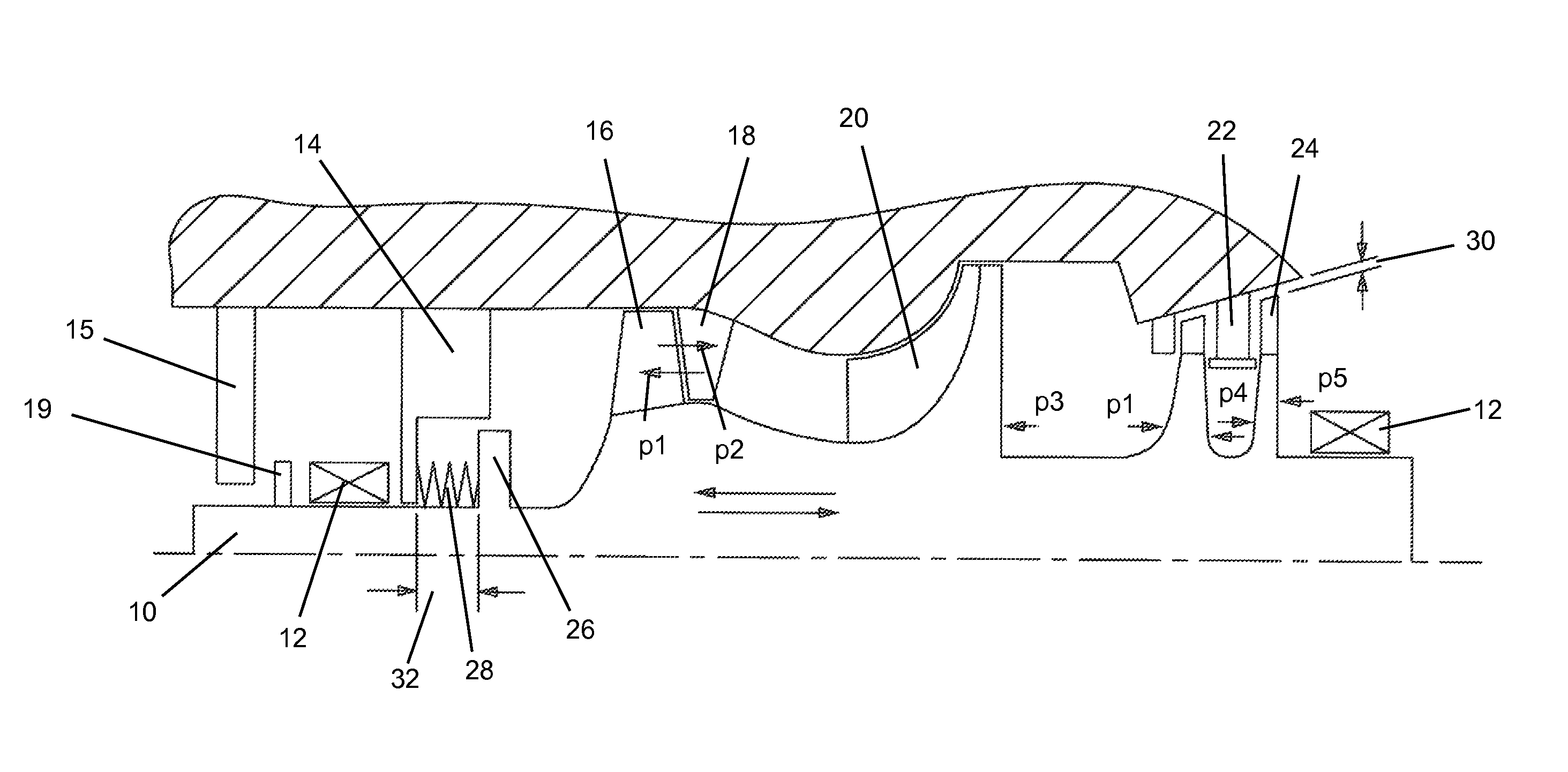
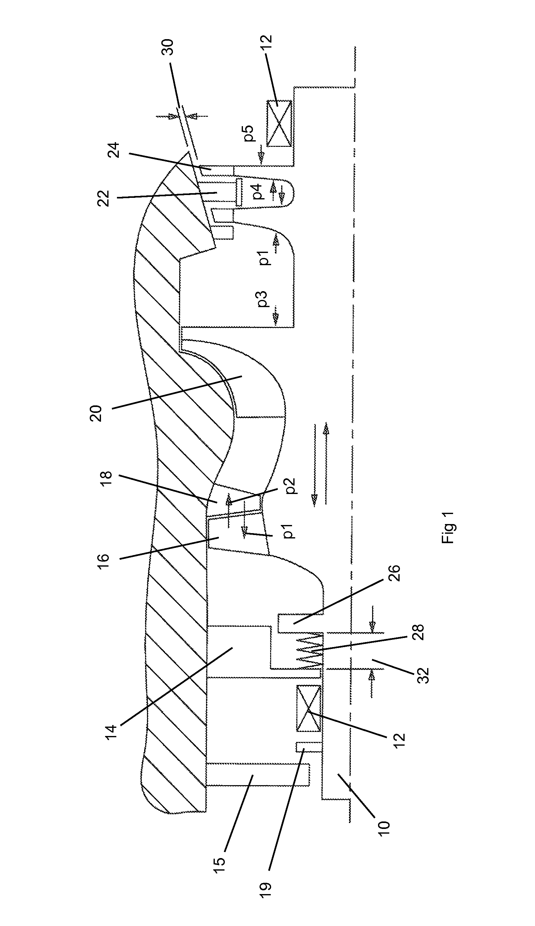
[0016]The present invention is a gas turbine engine having a blade tip clearance control to regulate the gap between rotating blade tips and the outer shroud in which the turbine blades and the outer shroud are conical in shape such that relative displacement produces a change in the gap spacing. The rotor shaft is biased in an axial direction by a spring member where extension of the spring results in an increase in the gap spacing. During operation of the engine, different pressures are developed that act on the rotor shaft. These various pressures will displace the rotor shaft against the force of the spring and decrease the gap spacing. No external controls or monitoring of variables are needed in the present invention. The blade tip clearance is self regulating especially during engine shut-down to prevent rub. In a second embodiment, the rotor shaft is aligned in a vertical direction so that the weight of the rotor shaft biases the turbine blades to increase the gap. A counter weight spring biases the rotor shaft to oppose the bias produced by the rotor shaft weight so that a lower pressure force acting on the rotor shaft is required to displace the rotor shaft and change the gap.

Problems solved by technology

The rotor shaft is biased in an axial direction by a spring member where extension of the spring results in an increase in the gap spacing.

Method used


Image

  • Rotor thrust balance activated tip clearance control system
  • Rotor thrust balance activated tip clearance control system
  • Rotor thrust balance activated tip clearance control system

Examples


Embodiment Construction

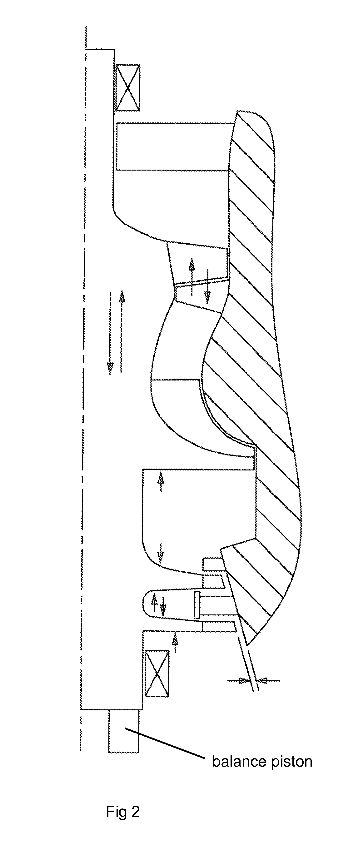
[0019]The gas turbine engine of the present invention includes an axially displacable rotor shaft in which the turbine blade tip clearance is adjusted to minimize leakage across the gap and to prevent rub between the tips and the outer shroud during shut-down of the engine. The gas turbine engine includes a rotor shaft 10 on which a compressor and a turbine blade arrangement rotates therewith. The compressor includes guide vanes 14 and 18 and compressor blades 16. The turbine includes turbine blades 24 and guide vanes 22. One stage of compressor blades and two stages of turbine blades are shown in the drawing for purposes of illustration. In an actual gas turbine engine, multiple stages of compressor and turbine blades are used.

[0020]The rotor 10 is supported by front and rear bearings 12. An outer shroud of the engine supports a guide vane 14, and the compressor vanes 18 and turbine vanes 22. A centrifugal pump 20 is located upstream of a combustor section. The axial compressor wit...


PUM


Abstract

A gas turbine engine with a rotor shaft that is moveable in an axial direction so change a blade tip clearance, where the rotor is displaced by a spring to increase the blade tip clearance and is displaced by a pressure created by the compressor and turbine during engine operation that will close the blade tip clearance. This is especially useful during engine shutdown to prevent blade tip rubbing against the stationary shrouds.

Description

CROSS-REFERENCE TO RELATED APPLICATIONS[0001]This application claims the benefit to an earlier filed Provisional Patent Application 60 / 794,172 filed on Apr. 20, 2006 and entitled ROTOR THRUST BALANCE ACTIVATED TIP CLEARANCE CONTROL SYSTEM.BACKGROUND OF THE INVENTION[0002]1. Field of the Invention[0003]The present invention relates to gas turbine engines, and more specifically to a system to control a blade tip clearance in the turbine section.[0004]2. Description of the Related Art Including Information Disclosed Under 37 CFR 1.97 and 1.98[0005]A gas turbine engine such as those used in industrial application for electric power production and those used in aerospace for aircraft propulsion operate at improved efficiency if the blade tip clearance is kept to a minimum to prevent leakage of the gas stream past the blades. The blade tip clearance gap is not a continuous gap length during engine operation. The gap length changes due to different thermal growth coefficients between the r...

Claims


Application Information

Patent Timeline
Patent Type & Authority Patents(United States)
IPC IPC(8): F01D11/16
CPCF01D11/22F01D25/168F04D29/052Y02T50/671F05D2260/52Y02T50/60
Inventor BROSTMEYER, JOSEPH
Owner FLORIDA TURBINE TECH
Learn More