
Low Track Pitch Write Module And Bidirectional Tape Head

a write module and low track pitch technology, applied in the field of thin film tape heads, can solve the problems of track misregistration, large gap pitch within the transducer array, and large weight of the transducer array, and achieve the effect of reducing the requirements for read gap spacing

Inactive Publication Date: 2011-09-15
INT BUSINESS MASCH CORP
View PDF41 Cites 16 Cited by
  • Summary
  • Abstract
  • Description
  • Claims
  • Application Information

AI Technical Summary

Benefits of technology

[0013]Read-after-write capability may be provided by mounting one or more separate read modules in a fixed relationship relative to a write module that comprises the write elements. If vertical write elements are used, one or more read element arrays having a vertical construction may be fabricated on a common substrate with the write elements. Adjacent read elements may be disposed in alternating vertical layers to reduce read gap spacing requirements.

Problems solved by technology

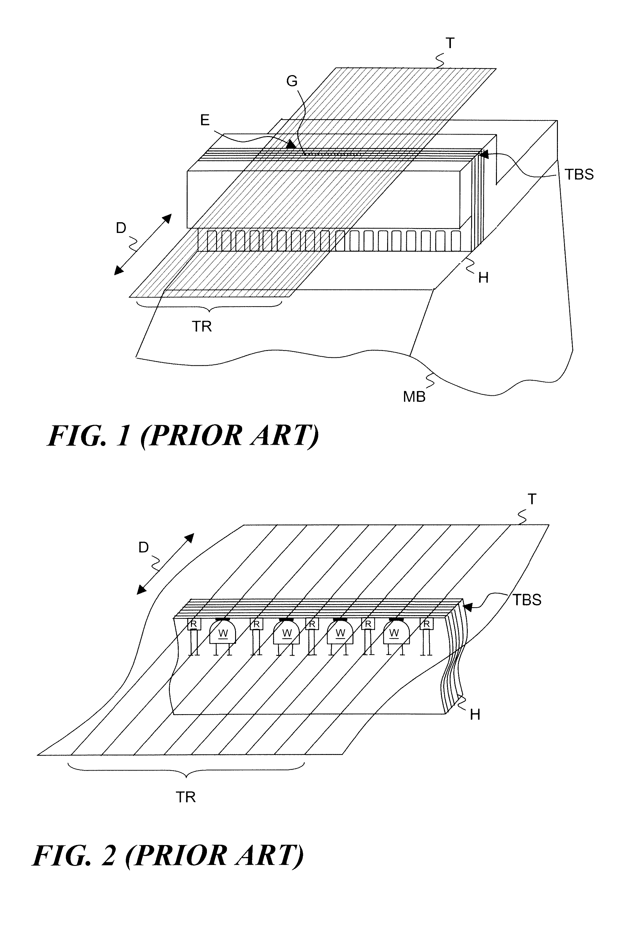
A disadvantage of vertical head constructions as described above is that the transducer element gaps at the TBS must be sufficiently spaced from each other to provide room for the major portion of the transducer element structure that is recessed behind the TBS.
These are also relatively bulky compared to the read gap structure at the TBS, although less so compared to write elements.
The problem is that the gap pitch within the transducer array is much larger than the gap width, such that for every track being read or written by the array, there will be space between the tracks where no transducing occurs.
Although the foregoing track writing techniques allow data to be densely packed on a tape, a continuing unresolved problem is track misregistration caused by tape dimensional changes between writing and reading operations.
These tape dimensional changes will widen or narrow the tape track spacing geometry, resulting in track misregistration with the tape head whose gap spacing geometry is substantially unchanged.
Although rotation of the tape head can be used to address the misregistration problem by changing the effective track pitch of the transducer array, this solution requires sophisticated mechanics and skew compensation circuitry.

Method used


Image

  • Low Track Pitch Write Module And Bidirectional Tape Head
  • Low Track Pitch Write Module And Bidirectional Tape Head
  • Low Track Pitch Write Module And Bidirectional Tape Head

Examples


Embodiment Construction

[0041]The invention will now be described by way of exemplary embodiments shown by the drawing figures (which are not necessarily to scale), in which like reference numerals indicate like elements in all of the several views.

[0042]Turning now to FIG. 4, a tape head 2 includes a planar write module 4 that may be used alone or optionally arranged with one or both of a pair of vertical read modules 6 and 8. The write module 4 has a write module tape bearing surface 10 for engaging a magnetic recording tape “T,” one edge of which is shown in FIG. 4. As additionally shown in FIGS. 5-7, the write module 4 has a planar head construction in which plural write elements 12 in the write module 4 each comprise plural thin film layers “L” oriented in generally parallel planar relationship with the write module tape bearing surface 10. It will be seen that the write elements 12 are arranged so that the transducing gaps (write gaps) 14 of adjacent write elements are generally aligned along an axis...


PUM

PropertyMeasurementUnit
gap sizeaaaaaaaaaa
gap sizeaaaaaaaaaa
lengthaaaaaaaaaa

Abstract

A low track pitch write module and bidirectional tape head for writing and / or reading data on a magnetic recording tape. The write module and tape head have a tape bearing surface for engaging the magnetic recording tape and plural write elements. The write elements are arranged so that the write gaps of adjacent write elements are spaced from each other by not more than approximately one write gap width, while being generally aligned along an axis that is perpendicular to a direction of movement of the magnetic recording tape. The write elements may have a planar or vertical construction comprising plural thin film layers oriented in generally parallel or perpendicular relationship with the tape bearing surface. One or more read element arrays may also be provided.

Description

BACKGROUND OF THE INVENTION[0001]1. Field of the Invention[0002]This invention relates to tape drive data storage systems. More particularly, the invention is directed to thin film tape heads for reading and writing data on magnetic recording tape.[0003]2. Description of the Prior Art[0004]Thin film tape heads for magnetic information storage systems (e.g., tape drives) have been constructed using the same fabrication techniques used by disk drive manufacturers. A characteristic of such construction is that the thin film layers which comprise the read and write transducer elements are oriented perpendicularly to the tape bearing surface (TBS) of the head. Such heads may be referred to as “vertical” heads due to the fact that the read and write gap portions are situated at the TBS, while the element layer structures extend vertically away from the TBS. In a vertical head with multitrack recording capability, plural transducer elements are commonly arranged side-by-side to form a line...

Claims


Application Information

Patent Timeline
Patent Type & Authority Applications(United States)
IPC IPC(8): G11B5/33
CPCG11B5/00826
Inventor BISKEBORN, ROBERT G.
Owner INT BUSINESS MASCH CORP
Learn More