
Modular electronically reconfigurable battery system

a battery system and module technology, applied in the field of module electronic reconfigurable battery systems, can solve the problems of the most energy and power density of lithium-ion (li-ion) technology, and achieve the effect of simple scaling of more and easy configuration

Active Publication Date: 2011-02-22
L 3 APPLIED TECH
View PDF21 Cites 41 Cited by
  • Summary
  • Abstract
  • Description
  • Claims
  • Application Information

AI Technical Summary

Benefits of technology

"The present invention provides an electronically reconfigurable battery that can be easily and quickly reconfigured to deliver different levels of power to various loads. The battery includes multiple battery modules that can be connected in series or parallel configurations, and a DC current limiting section or a single stage current limiting converter to control the current outside the range of the battery technology used. The battery can be built in a modular form and can be redundant and fault tolerant. The system also includes a voltage scalable arm that can be connected in a star or H configuration, and can isolate the loads from the main system load. The energy from the battery can be directed to flow out the output in discrete energy packets that are time multiplexed on the output connection side. The invention provides a more efficient and flexible solution for converting power from a battery to a suitable load."

Problems solved by technology

Of these systems, the lithium-ion (Li-ion) technology is the most energy and power dense.

Method used


Image

  • Modular electronically reconfigurable battery system
  • Modular electronically reconfigurable battery system
  • Modular electronically reconfigurable battery system

Examples


example

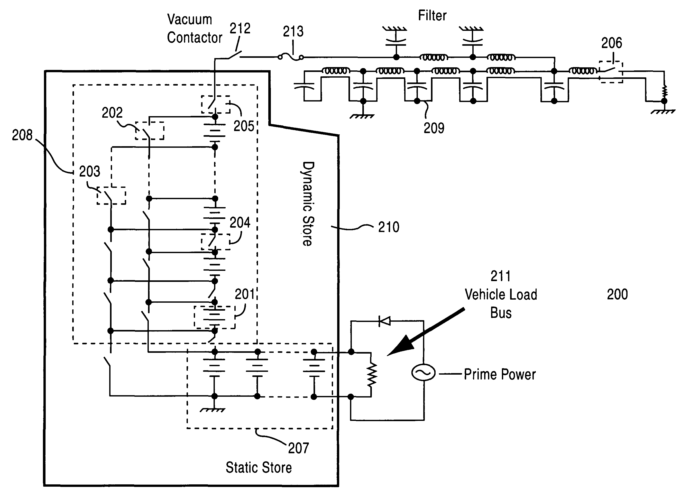
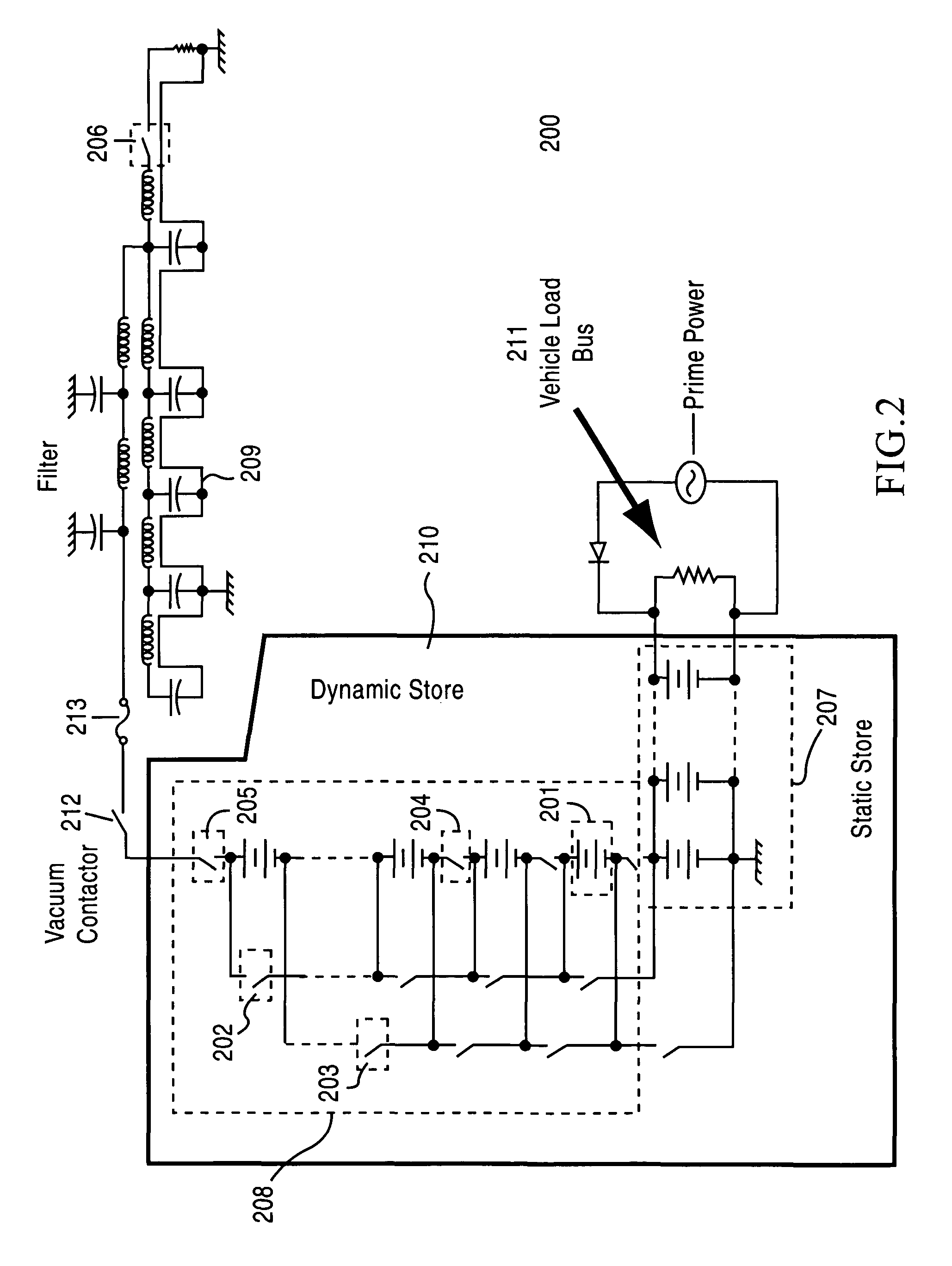
[0057]Assuming a 20-ton class vehicle and extrapolating from CHPS requirements, a conceptual design of an ERB for a hybrid electric vehicle with an EMA system has the following requirements: 1) Deliver up to 400 kW to the vehicle bus at 1 kV in parallel operation; 2) Recharge a 150-kJ capacitive store to 10 kV in 300 milliseconds; and 3) Support 30-45 minute silent operation at 80 kW. These requirements mandate the use of very high energy and power density batteries. Two candidate batteries are the HP series of lithium ion batteries being developed by SAFT and the lithium polymer batteries produced by Ultralife Batteries, Inc. for use in cell phones. The SAFT batteries have a slight advantage in usable power density and packaging for military use, whereas the Ultralife batteries have an advantage in cost (0.15-0.2 cents / J, 5-8 cents / Wpk, owing to volume production) and a potential for more compact packaging (prismatic) in ERB service.

[0058]The ERB system in this case constitutes onl...


PUM


Abstract

An electronically reconfigurable battery includes a number of battery modules selectively interconnected by a number of electronic switches, wherein a selectable number of battery modules may be connected either in a series configuration or in a parallel configuration, as a result of placing selected switches of said plurality of switches in open states or closed states. In a parallel configuration, the battery provides power to a primary load, such as a propulsion load for a vehicle. In a series configuration, the battery is configured to provide a high voltage and high power output to a short-term and / or pulsed load, such as an additional load provided on the vehicle. Current from the battery is limited in one of three ways: a) by the batteries themselves; b) a current limiting device or system in series with the total erected battery; or c) a single level power converter or current limiter that is used to erect and charge the capacitor bank in a sequential one level at a time manner until the battery is fully erected and the capacitor is fully charged.

Description

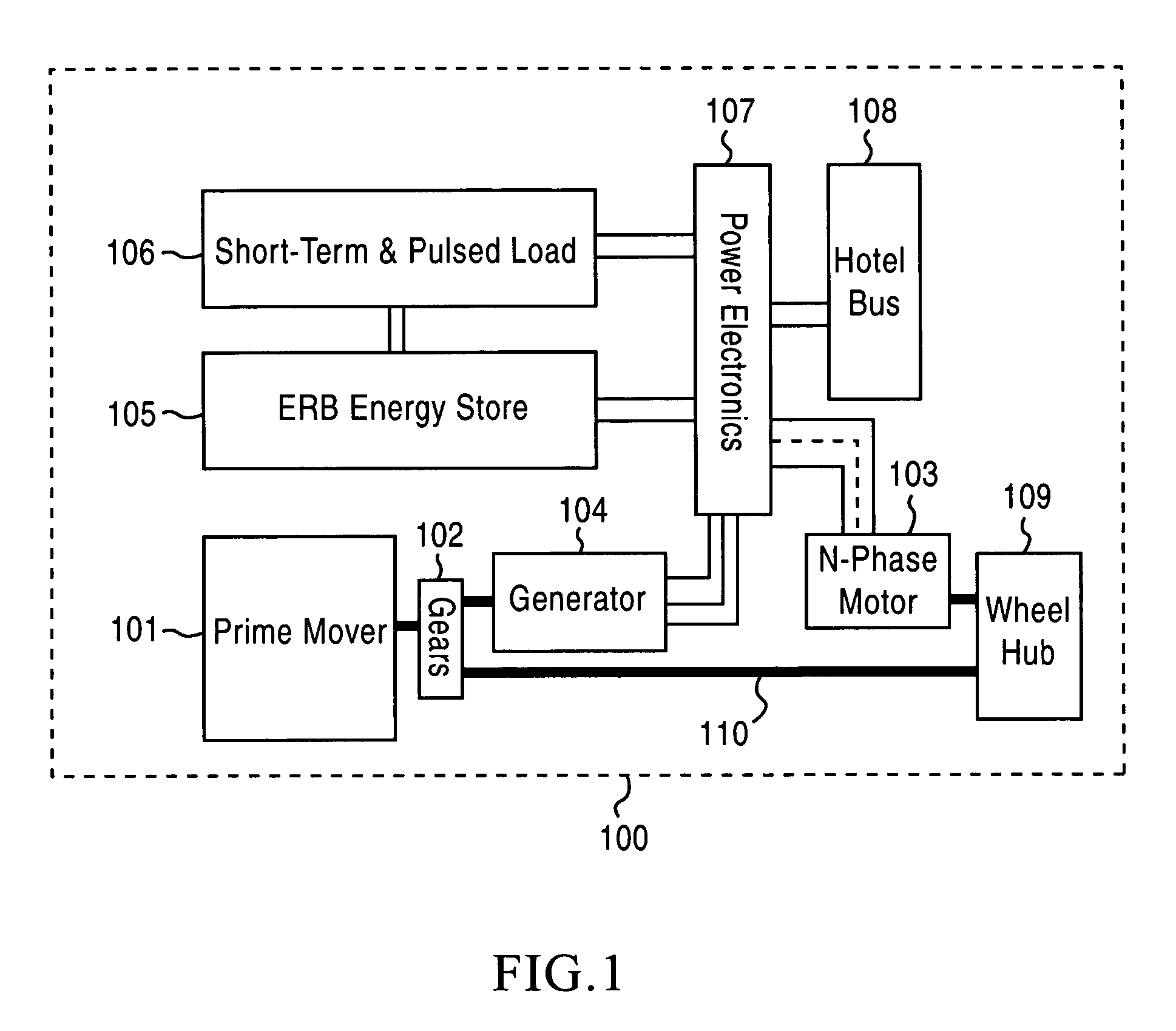
CROSS-REFERENCE TO RELATED APPLICATIONS[0001]This application claims priority to and is a continuation-in-part of U.S. patent application Ser. No. 10 / 631,017, filed on Jul. 31, 2003, the entire contents of which are incorporated herein by reference.BACKGROUND OF THE INVENTION[0002]1. Field of the Invention[0003]The present invention relates to electrical energy storage systems and, in particular, to battery packs composed of multiple battery modules with adjustable configurations.[0004]2. Description of the Related Art[0005]Hybrid electric vehicles (HEVs), hybrid electric ships and boats (such as the QE2) afford greater fuel efficiency than vehicles or vessels having only a prime mover (e.g., diesel or gasoline engine, gas turbine and fuel cell). Greater efficiency is obtained by using an energy store to level the load on the prime mover-providing peaking power to an electric motor, or storing energy during low power prime mover operation or during regenerative braking.[0006]A well-...

Claims


Application Information

Patent Timeline
Patent Type & Authority Patents(United States)
IPC IPC(8): H02J1/00F41B6/00H02J7/00
CPCF41B6/00H02J7/0024B60K6/00Y10T307/653Y02T10/7055Y02T10/70Y02P70/50
Inventor WEIDENHEIMER, DOUGLAS M.DONEGAN, KEVIN J.MORTON, DAVID WAYNE
Owner L 3 APPLIED TECH
Learn More