
LED light source with light-directing structures

a technology of led light source and light-directing structure, which is applied in the direction of discharge tube luminescnet screen, electric discharge lamp, lighting and heating apparatus, etc., can solve the problems of uneven light intensity, poor color mixing, and dark regions near the edges of light-guiding plate, so as to improve light mixing and enhance light mixing.

Active Publication Date: 2011-02-15
AVAGO TECH INT SALES PTE LTD
View PDF9 Cites 7 Cited by
  • Summary
  • Abstract
  • Description
  • Claims
  • Application Information

AI Technical Summary

Benefits of technology

The invention is a new LED light source that uses a nanolens to improve the mixing of light from the LEDs. This can be further enhanced by adding a diffusant layer or reflectors to the light source. The technical effect of this invention is better and more complete mixing of light from the LEDs, resulting in a more uniform and complete light output.

Problems solved by technology

This approach has several drawbacks including poor color mixing, uneven light intensity, and the presence of dark regions near the edges of the light guide plate.

Method used


Image

  • LED light source with light-directing structures
  • LED light source with light-directing structures
  • LED light source with light-directing structures

Examples


Embodiment Construction

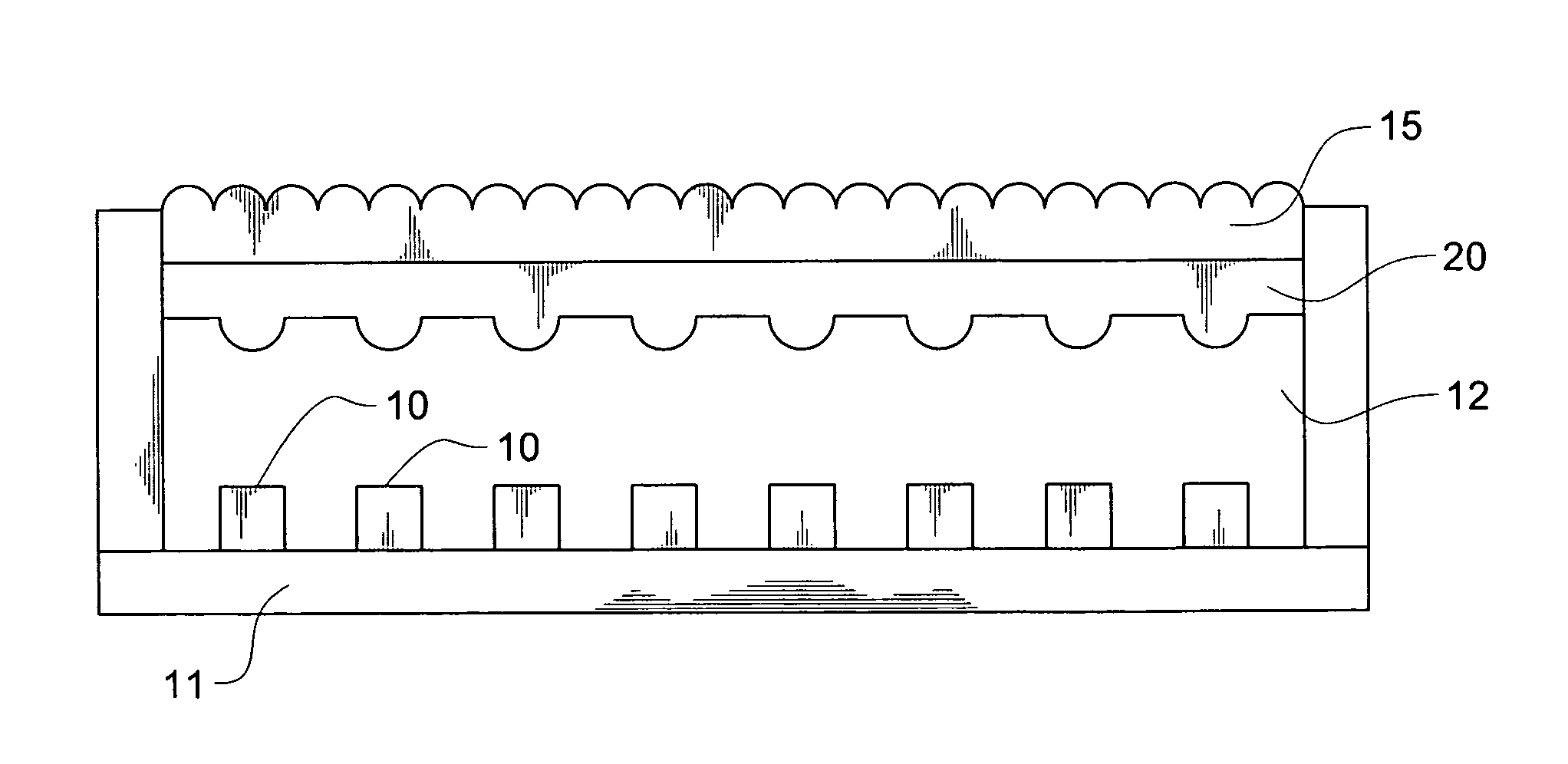
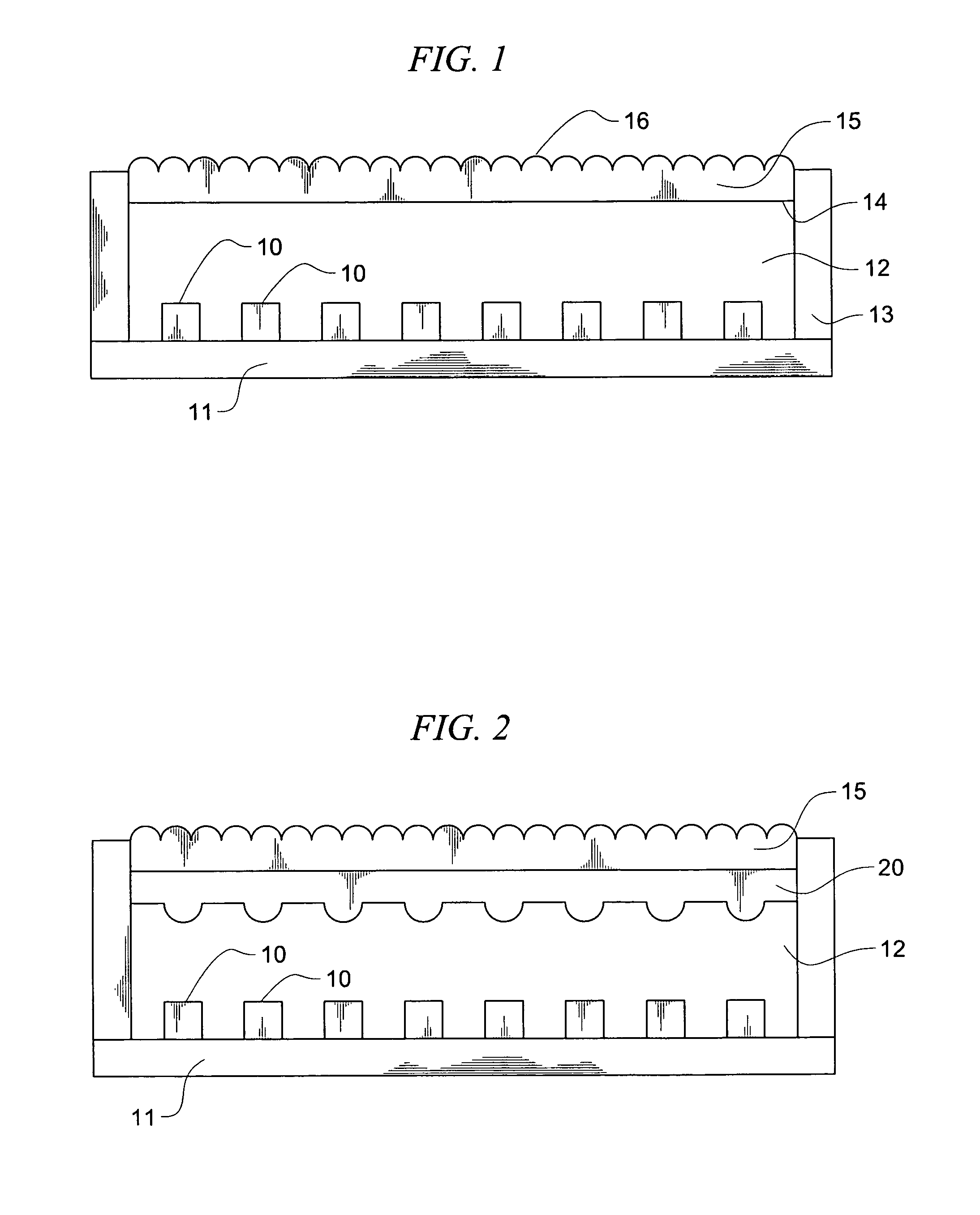
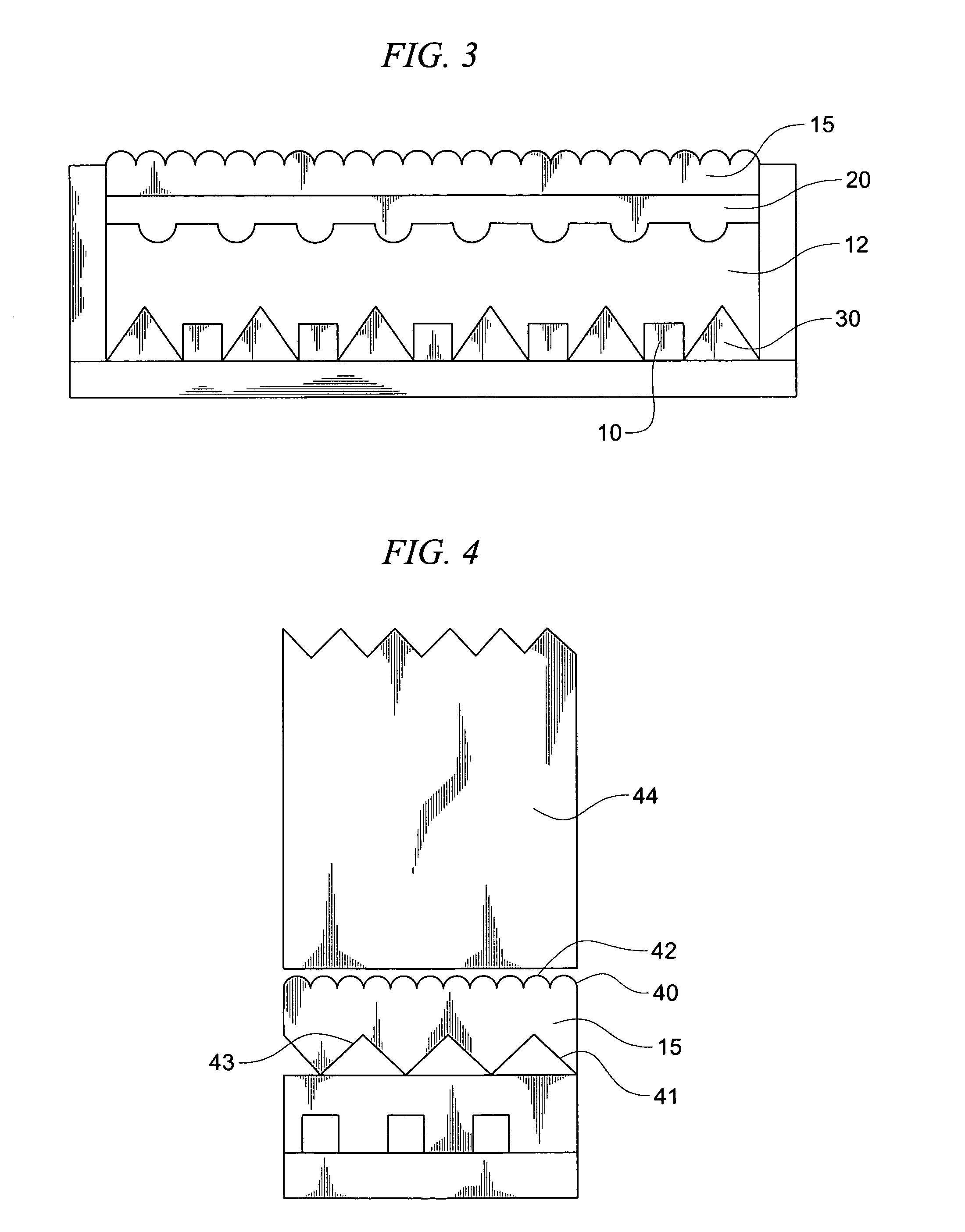
[0013]FIG. 1 shows an embodiment of the invention. In this embodiment, light emitting diode chips 10 are attached to a substrate 11 and at least partially encapsulated with an encapsulant 12. Depending on the nature of the encapsulant 12, a casing 13 may be used to support the encapsulant 12. Associated with the upper surface 14 of the encapsulant 12 is a nanolens layer 15. The nanolens layer is designed to redirect light generated by chips 11 causing mixing of the light. The mixing may occur in a number of regions including within the nanolens layer 15, within the encapsulant 12, within a space between the light source and a light guide, or any combination of these regions.

[0014]The light-directing nanolens layer 15 may be formed by nano imprinting the surface of the encapsulant 12 to produce the desired structures, or it may comprise a separate layer of material which has been shaped to have the desired structures. This separate nanolens layer will typically be prepared from a tra...


PUM


Abstract

A light source that has improved light mixing. The light source uses a nanolens layer in conjunction with an LED light source to enhance the mixing of the colored light emitting from the LED light source.

Description

CROSS-REFERENCE TO RELATED APPLICATIONS[0001]Not applicable.TECHNICAL FIELD[0002]The invention relates in general to a light-emitting diode light source, and is specifically a light-emitting diode light source that comprises a nanolens layer in association with an encapsulated light emitting diode chip to improve light mixing.BACKGROUND OF THE INVENTION[0003]Light-emitting diodes generally emit light in a specific color or range of wavelengths. To produce a white light, it is usually necessary to combine or mix the light from plural LEDs which emit different colors, for example, red, green and blue. Initially, light mixing was accomplished by placing LEDs of different colors next to each other such that the light emitted by each LED would mix with the light from the others. A common structure associated with such mixing is a light guide.[0004]This approach has several drawbacks including poor color mixing, uneven light intensity, and the presence of dark regions near the edges of th...

Claims


Application Information

Patent Timeline
Patent Type & Authority Patents(United States)
IPC IPC(8): H01L51/50H01L33/00H01L33/58
CPCF21K9/00H01L33/58F21V5/008F21K9/68F21K9/69F21Y2105/10F21Y2105/12F21Y2113/13F21Y2115/10
Inventor KUAN, YEW CHEONGPANG, SIEW ITCHUIN, NG FOOKCHEW, TONG FATTMOK, THYE LINN
Owner AVAGO TECH INT SALES PTE LTD
Learn More