
Systems and methods for reducing noise in an imaging catheter system

a technology of imaging catheter and noise reduction, applied in the field of medical imaging systems, can solve problems such as signal distortion in other devices, and achieve the effects of reducing noise, reducing noise caused by transmission line exposure, and attenuating noise introduced in the transmission lin

Active Publication Date: 2011-02-15
SCI MED LIFE SYST
View PDF29 Cites 1 Cited by
  • Summary
  • Abstract
  • Description
  • Claims
  • Application Information

AI Technical Summary

Benefits of technology

[0010]The present invention provides systems and methods for reducing noise in an imaging catheter system. In an embodiment, a catheter comprises an imaging transducer and a transmission line within the catheter to transmit signals to and from the transducer. To reduce noise caused by exposure of the transmission line to external interference, a choke balun is coupled to the proximal end of the transmission line. The choke balun passes the desired transducer signal while attenuating noise introduced in the transmission line. In an embodiment, the transmission line comprises a coaxial cable having a center conductor surrounded by a shield. In this embodiment, the choke balun attenuates unwanted current induced in the shield of the coaxial cable by external electric fields from neighboring devices.
[0011]In another embodiment, the signal from a rotating imaging transducer of the catheter is coupled to a motor drive unit by a slip ring assembly. In this embodiment, the transducer signal is passed through first and second transformers placed on opposite sides of the slip ring assembly to reduced noise from the slip ring assembly. The slip ring assembly preferably comprises a mercury slip ring assembly.
[0012]In another embodiment, a balun is coupled to the second transducer. This balun may be used to convert the balanced transducer signal into a single-ended signal and / or to reject common-mode noise to further improve the signal.
[0013]In another embodiment, the catheter includes a position sensor to track the position of the catheter. The position sensor is coupled to a second transmission line within the catheter to transmit signals to and from the position sensor. To further reduce noise, a second choke balun is coupled to the proximal end of the second transmission line.

Problems solved by technology

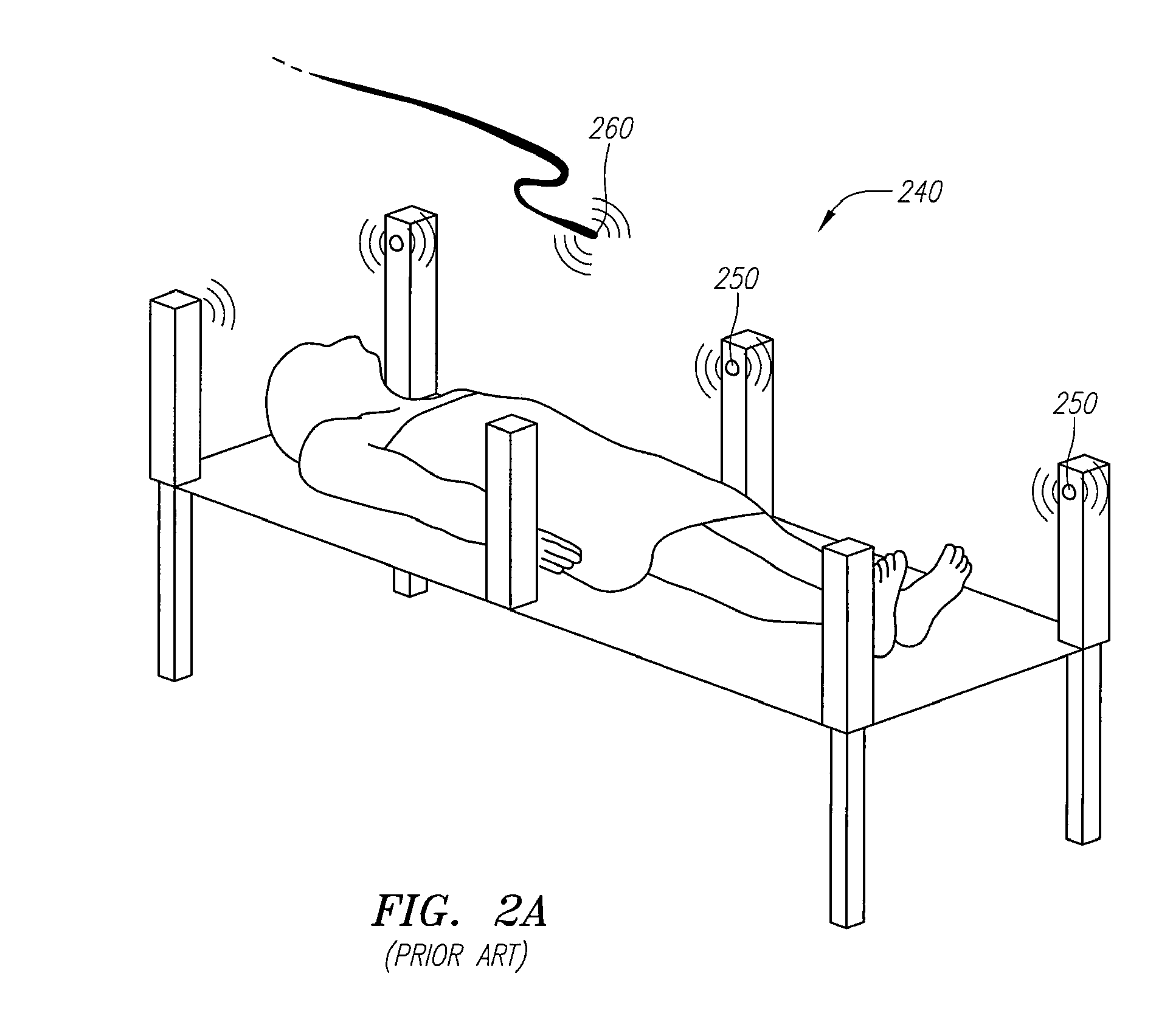
However, each of these devices generate an electromagnetic field, and if they are situated sufficiently close, the respective fields can cause signal distortion in other devices.

Method used


Image

  • Systems and methods for reducing noise in an imaging catheter system
  • Systems and methods for reducing noise in an imaging catheter system
  • Systems and methods for reducing noise in an imaging catheter system

Examples


Embodiment Construction

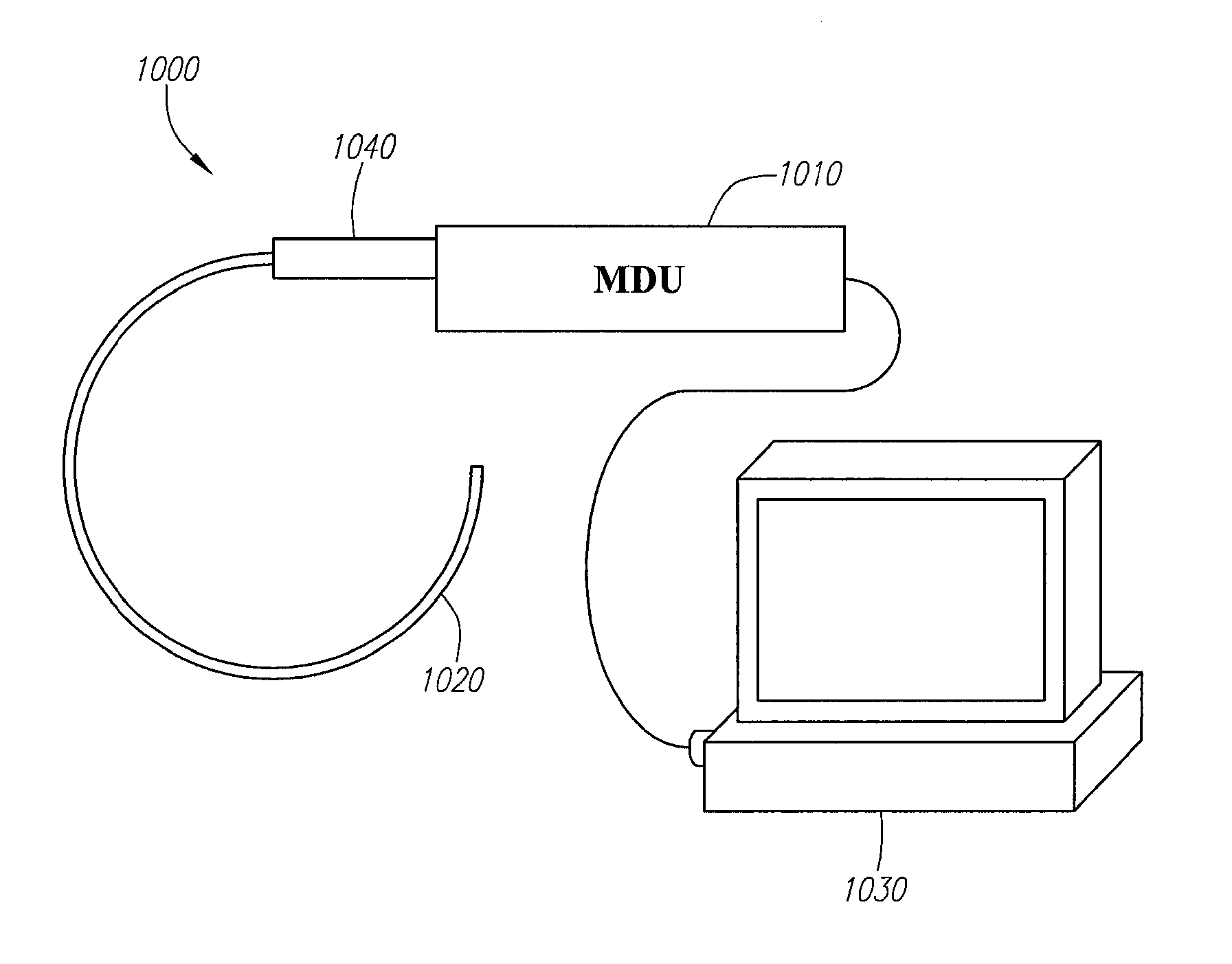
[0026]Turning to FIG. 3, an illustration of a medical imaging system 1000 in accordance with a preferred embodiment is shown. The system 1000 comprises an imaging catheter or guidewire 1020, such as those described above, which is adapted to be inserted into a lumen of the body and preferably within the vascular system of the body. The imaging catheter 1020 detachably connects to a motor drive unit (“MDU”) 1010 via a hub 1040. The MDU 1010 is electrically coupled to a signal processing console 1030. The MDU 1010 includes a motor (not shown) that couples to the drive shaft of the catheter 1020 for rotating the transducer. A more detailed description of the MDU is provided in U.S. Pat. No. 6,261,246, filed on Sep. 28, 1998, which is hereby incorporated by reference in its entirety.

[0027]As mentioned above, in a typical operating environment, other electronic devices are situated near the imaging system 1000, and their respective electromagnetic fields may introduce distortion into the...


PUM


Abstract

The present invention provides systems and methods for reducing noise in an imaging catheter system. In an embodiment, a catheter comprises an imaging transducer and a transmission line within the catheter to transmit signals to and from the transducer. To reduce noise caused by exposure of the transmission line to external interference, a choke balun is coupled to the transmission line. In another embodiment, the signal from a rotating imaging transducer of the catheter is coupled to a motor drive unit by a slip ring assembly. The transducer signal is passed through first and second transformers placed on opposite sides of the slip ring assembly to reduce noise from the slip ring assembly. In another embodiment, the catheter includes a position sensor to track the position of the catheter. The position sensor is coupled to a second choke balun to further reduce noise.

Description

RELATED APPLICATION[0001]This application claims the benefit of U.S. Provisional Patent Application Ser. No. 60 / 735,374, filed on Nov. 12, 2005.FIELD OF THE INVENTION[0002]The field of the invention relates to medical imaging systems, and more particularly to systems and methods for reducing noise in an imaging catheter system.BACKGROUND OF THE INVENTION[0003]Intraluminal, intracavity, intravascular, and intracardiac treatments and diagnosis of medical conditions utilizing minimally invasive procedures are effective tools in many areas of medical practice. These procedures are typically performed using imaging and treatment catheters that are inserted percutaneously into the body and into an accessible vessel of the vascular system at a site remote from the vessel or organ to be diagnosed and / or treated, such as the femoral artery. The catheter is then advanced through the vessels of the vascular system to the region of the body to be treated. The catheter may be equipped with an im...

Claims


Application Information

Patent Timeline
Patent Type & Authority Patents(United States)
IPC IPC(8): A61B8/14
CPCA61B8/12A61B5/06A61B2562/222A61B5/062
Inventor MASTERS, DONALD
Owner SCI MED LIFE SYST
Learn More