System for attaching electronic components to molded interconnection devices

a technology for connecting devices and electronic components, applied in the direction of printed circuit non-printed electric components, semiconductor/solid-state device details, final product manufacturing, etc., can solve the problems of smds exhibiting a tendency to slide off of the mid, only secure components, and difficult reflow soldering process

Inactive Publication Date: 2011-01-25
TE CONNECTIVITY CORP
View PDF9 Cites 20 Cited by
  • Summary
  • Abstract
  • Description
  • Claims
  • Application Information

AI Technical Summary

Problems solved by technology

Additionally, the components are only secure on the surface or substrate to which they are mounted following the low heat or ultraviolet radiation curing process.
While effective with PCBs, the reflow soldering process is problematic when used with other substrates such as molded interconnection devices (MID).
One complication associated with the reflow soldering process occurs when there are multiple, non-parallel or non-horizontal surfaces to which SMDs are to be attached.
If the surfaces on an MID to which the SMT components are to be attached are not all horizontally oriented, SMDs may exhibit a tendency to slide off of the MID as the solder paste begins to flow.
Movement of the components in this manner is highly undesirable and may result in the assembly of a non-functional or otherwise faulty device.

Method used


Image

  • System for attaching electronic components to molded interconnection devices
  • System for attaching electronic components to molded interconnection devices

Examples


Embodiment Construction

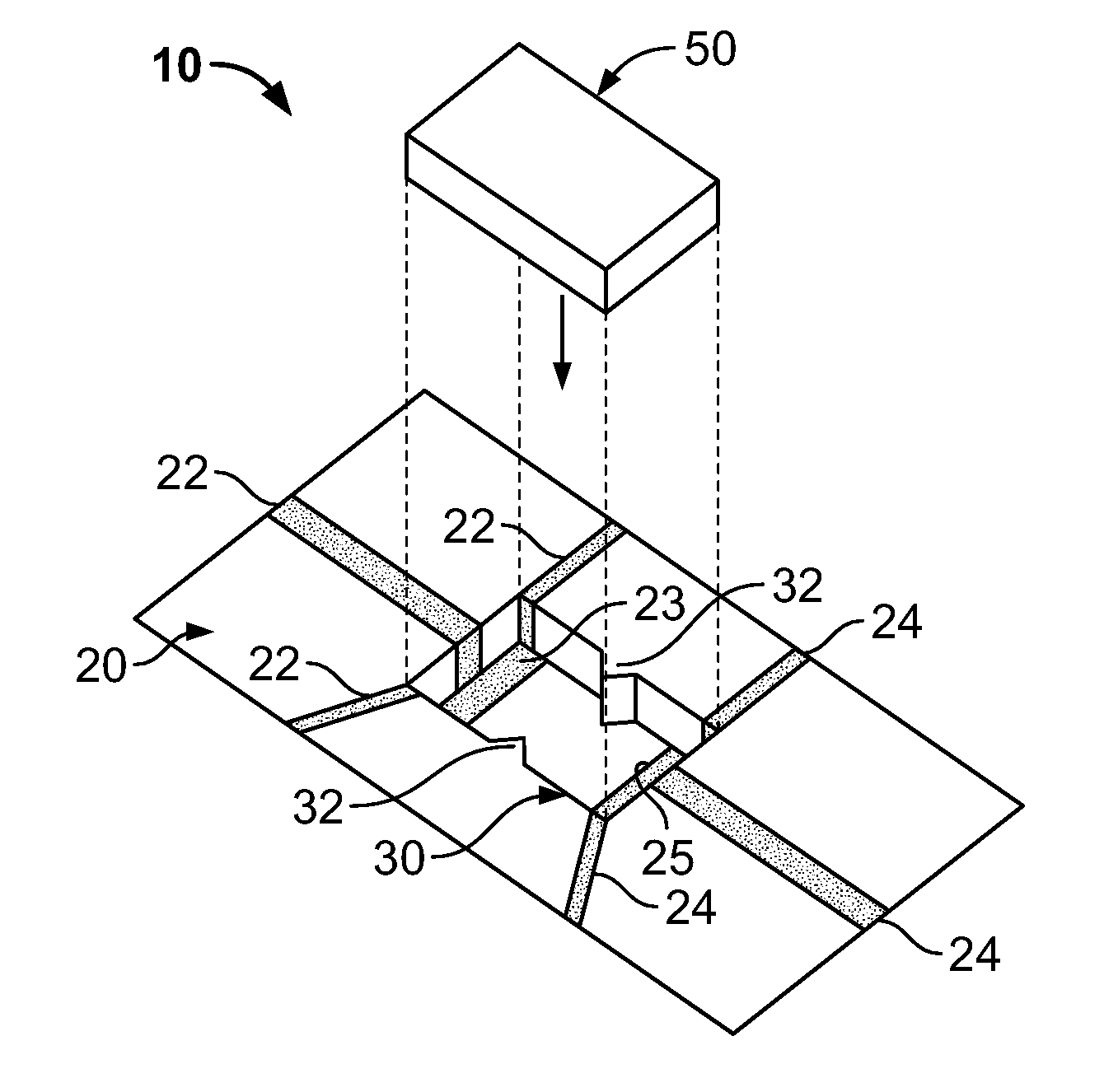
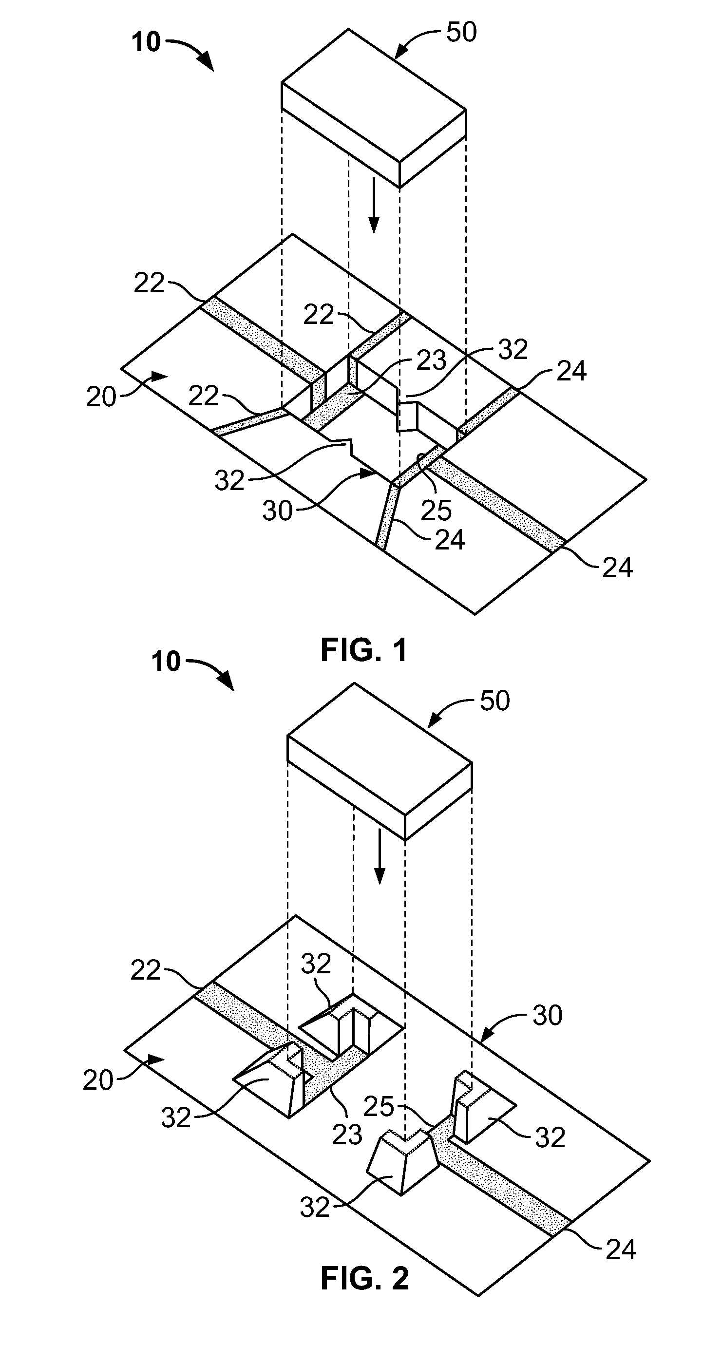
[0013]Exemplary embodiments of the present invention are now described with reference to the Figures. Reference numerals are used throughout the detailed description to refer to the various elements and structures. In other instances, well-known structures and devices are shown in block diagram form for purposes of simplifying the description. Although the following detailed description contains many specifics for the purposes of illustration, anyone of ordinary skill in the art will appreciate that many variations and alterations to the following details are within the scope of the invention. Accordingly, the following embodiments of the invention are set forth without any loss of generality to, and without imposing limitations upon, the claimed invention.

[0014]The present invention relates to a system and method for quickly and securely mounting electrical devices on non-horizontal substrates. With reference to the Figures, FIGS. 1-2 provide somewhat simplified representations of ...


PUM

PropertyMeasurementUnit
electrically conductiveaaaaaaaaaa
electricalaaaaaaaaaa
non-conductiveaaaaaaaaaa

Abstract

A system for connecting electrical devices to one another is provided. This system includes a horizontal or non-horizontal substrate and an anchor connected to or formed integrally with the substrate. The anchor is either a raised structure or a recessed structure, and further includes at least one retention member formed integrally with the anchor. At least one electronic component is mounted within the anchor and the at least one retention member secures the component to the substrate. At least one electrical trace is disposed on the substrate and the at least one electrical trace extends into the anchor, contacts the at least one electronic component, and forms an electrical connection between the substrate and the at least one electronic component.

Description

BACKGROUND OF THE INVENTION[0001]The described invention relates in general to a system for attaching electrical components or electronic components to a substrate and more specifically to a system, device, and method for securing surface-mount devices to molded interconnection devices during affixation by reflow soldering or other methods.[0002]Surface mount technology (SMT) is a known industrial process for constructing electronic circuits in which electrical or electronic components are mounted directly onto a substrate such as a printed circuit board (PCB). Electronic components that are suitable for mounting on such substrates are known as surface-mount devices or “SMDs”. At the positions where SMDs are to be mounted, typical PCBs include flat, electrically conductive pads referred to as solder pads. During the construction process, solder paste is first applied to all the solder pads; then, if components are to be mounted on the second side, a numerically controlled machine pl...

Claims


Application Information

Patent Timeline
Patent Type & Authority Patents(United States)
IPC IPC(8): H05K7/04
CPCH05K1/183H05K3/303H05K1/0284H05K3/301H05K2201/09045Y10T29/49137H05K2201/1059H05K2201/10636H05K2203/167Y10T29/49002H05K2201/09118Y02P70/50
Inventor WEBER, RONALD MARTINHORST, SHELDON LYNN
Owner TE CONNECTIVITY CORP
Why Eureka
Try Eureka