
Double-tuned circuit

a double-tuned circuit and circuit technology, applied in the direction of discontnuous tuning with seperate pretuned circuits, television systems, printed circuit non-printed electric components association, etc., can solve the problems of low work efficiency, low coupling degree, and inability to make both coils close enough to obtain sufficient coupling, so as to improve the frequency precision of an image trap and optimize the coupling degree , the effect of uniform selectivity

Inactive Publication Date: 2011-01-25
ALPS ALPINE CO LTD
View PDF6 Cites 5 Cited by
  • Summary
  • Abstract
  • Description
  • Claims
  • Application Information

AI Technical Summary

Benefits of technology

The patent describes a double-tuned circuit that includes two air-cored coils that are opposed to each other. The circuit is designed to increase the coupling degree between the coils and improve frequency precision. This is achieved by adding a first conductive pattern that is adjacent to the first coil and connected to ground. The pattern width can be adjusted to optimize the coupling degree and improve selectivity among channels. The technical effect of this design is to improve the performance of the double-tuned circuit and make it more efficient in its use.

Problems solved by technology

However, it is difficult to make both coils close enough to obtain sufficient coupling due to the restriction of the coil inserting holes on the substrate.
For this reason, it is necessary to adjust the tuning coils L2 and L3 fixed to the coil inserting holes so as to bring them closer, work efficiency is low, and there is a productivity problem.
In addition, such a double-tuned circuit has an influence on the frequency precision of an image trap formed in the tuned circuit, and thus it is difficult to obtain a uniform disturbance blocking characteristic within a reception band.

Method used


Image

  • Double-tuned circuit
  • Double-tuned circuit
  • Double-tuned circuit

Examples


Embodiment Construction

[0027]Hereinafter, preferred embodiments of the disclosure will be described in detail with reference to the accompanying drawings.

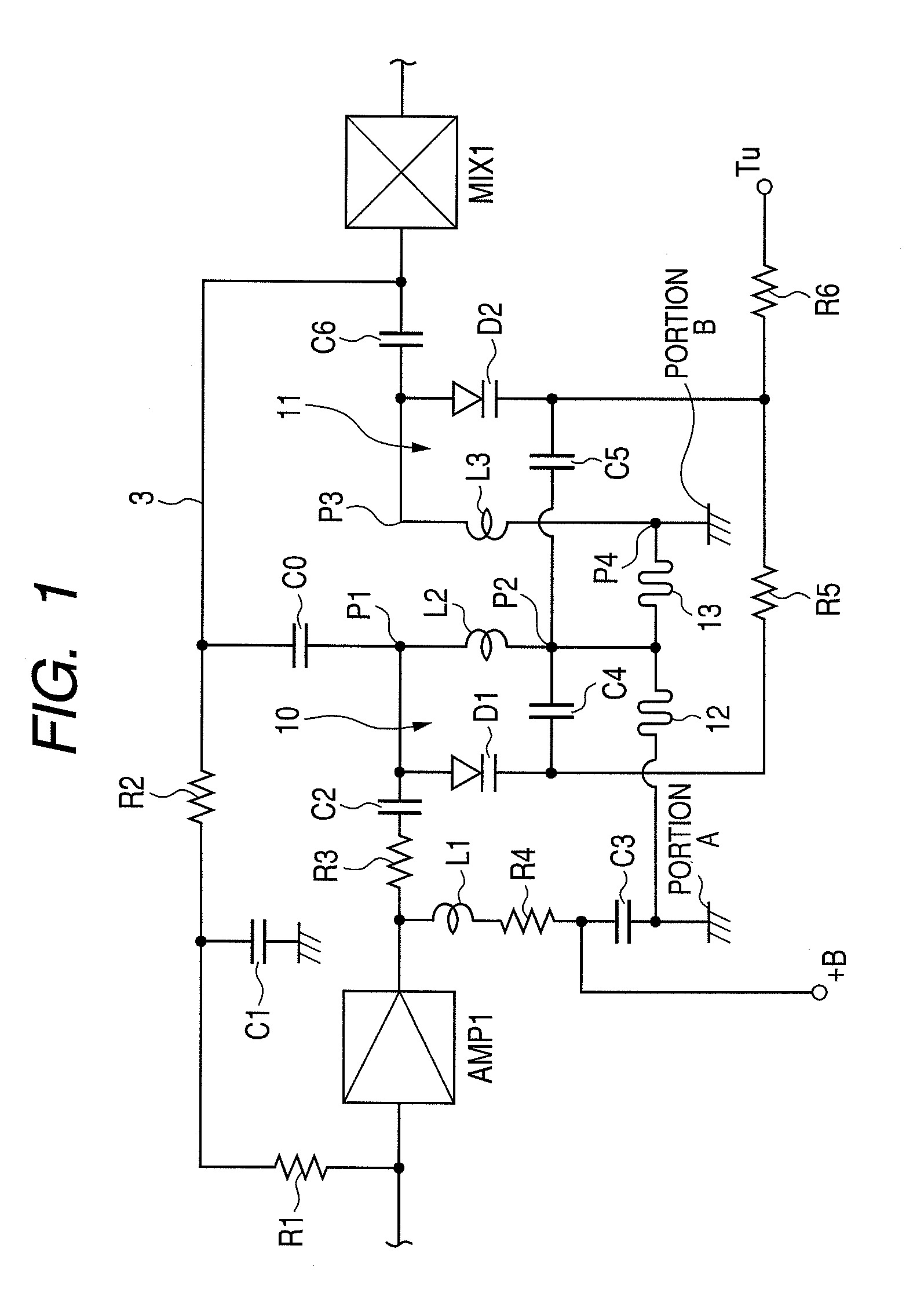
[0028]FIG. 1 is a diagram illustrating a double-tuned circuit of a television tuner according to an embodiment. The same reference numerals and signs are given to the same elements as those of the double-tuned circuit shown in FIG. 9, and overlapping description is avoided.

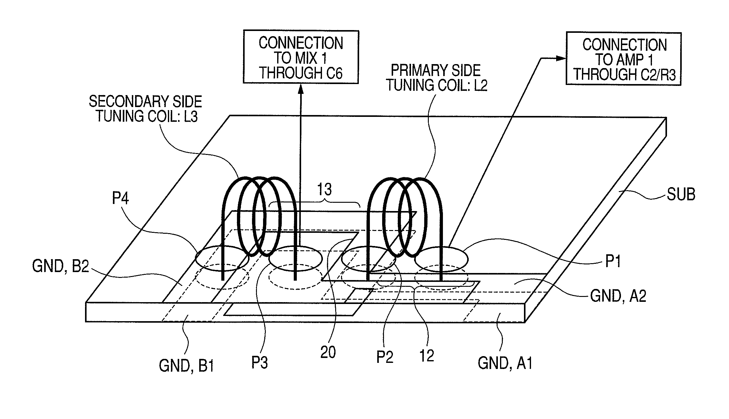
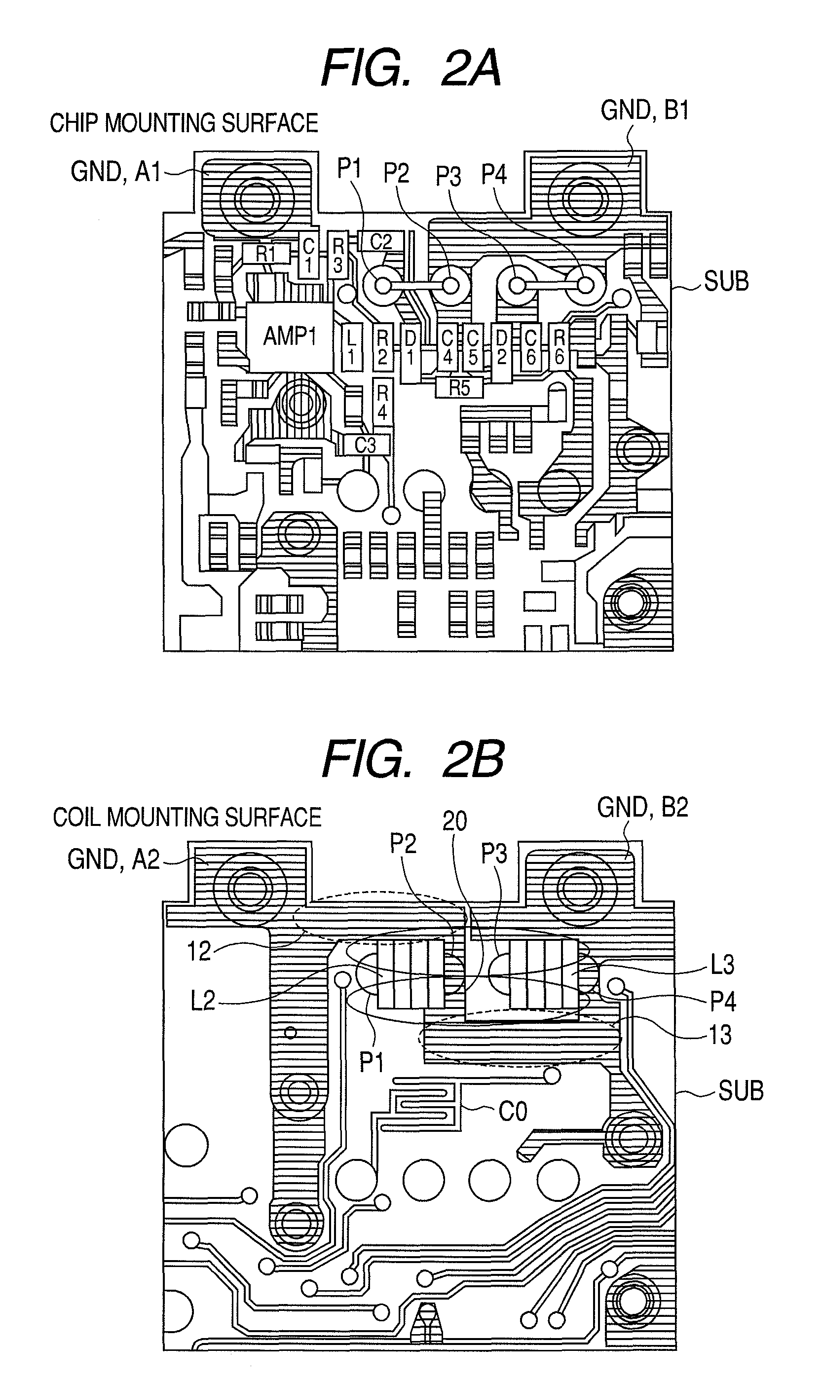
[0029]The double-tuned circuit of the television tuner according to the embodiment includes a primary side tuned circuit 10 and a secondary side tuned circuit 11, and one opening end of a tuning coil L2 as a first air-cored coil and one opening end of a tuning coil L3 as a second air-cored coil which are opposed and capable of being coupled to each other. A copper foil pattern 12 as a first conductive pattern is formed parallel to the tuning coil L2 of the primary side tuned circuit 10 on one side of the tuning coil L2, and a copper foil pattern 13 as a second conductive pattern is for...


PUM

PropertyMeasurementUnit
frequencyaaaaaaaaaa
frequencyaaaaaaaaaa
frequency selectivityaaaaaaaaaa

Abstract

A double-tuned circuit includes a primary side tuned circuit having a first air-cored coil and a secondary side tuned circuit having a second air-cored coil. The first air-cored coil and the second air-cored coil are opposed to each other so that one opening end of the first air-cored coil and one opening end of the second air-cored coil are capable of being coupled to each other on a coil mounting surface. The coil mounting surface is provided with a first conductive pattern formed adjacent to the first air-cored coil in a direction perpendicular to an arrangement direction of the first and second air-cored coils, and both ends of first conductive pattern are connected to a ground.

Description

CROSS REFERENCE TO RELATED APPLICATIONS[0001]The present application contains subject matter related to and claims priority to Japanese Patent Application No. 2008-173434 filed in the Japanese Patent Office on Jul. 2, 2008, the entire contents of which being incorporated herein by reference.BACKGROUND[0002]1. Technical Field[0003]The present invention relates to a double-tuned circuit used for a tuner such as a television receiver.[0004]2. Related Art[0005]There is known a double-tuned circuit of a television tuner in which a trap circuit for attenuating an image signal is formed. FIG. 9 is a circuit diagram illustrating an RF double-tuned circuit having an image trap formed therein. A television reception signal is input to a high frequency amplifier AMP1 through an antenna tuned circuit (not shown), and an output of the high frequency amplifier AMP1 is input to a primary side tuned circuit 1 of the RF double-turned circuit. A secondary side tuned circuit 2 is coupled to the primar...

Claims


Application Information

Patent Timeline
Patent Type & Authority Patents(United States)
IPC IPC(8): H01F5/00H03J3/24H04B1/18H04N5/44
CPCH01F5/00H03J5/244H05K1/18H05K2201/1003H05K2201/10265H05K2201/10522
Inventor YAMAMOTO, MASAKI
Owner ALPS ALPINE CO LTD
Learn More