Real time oil reservoir evaluation using nanotechnology

Inactive Publication Date: 2011-01-25
NASA
View PDF8 Cites 38 Cited by
  • Summary
  • Abstract
  • Description
  • Claims
  • Application Information

AI Technical Summary

Benefits of technology

[0009]This technology will provide two-dimensional fluid measurements by monitoring the chemical composition in gas or liquid phase and the physical properties of oil level in the wells to have comprehensive digital information from each well that distributed in the reservoir with a horizontal extent of around 1-10 miles and 2-2000 feet in depth. Because the chemical and physical measurement are digital, satellite communications technology can be utilized to bridge the distance between people and data. Reservoir data can be centralized to allow an oil and / or gas company and its clients to monitor and analyze underbalanced drilling projects without traveling to the wellsite. This technology can reduce risk, cut the amount of time needed for carrying out exploratory operations, and reduce the size of a reporting system placed in a wellsite down-hole.

Problems solved by technology

Current mechanical, electromagnetic or optical sensor technologies are relatively low-tech and passive, and do not acquire data at sufficient distances to permit reservoir managers to fully comprehend the chemical composition, volume and dynamics of the petroleum in a given reservoir.
There is no tool or methodology that can provide the information about the quality of the oil such as hydrocarbon content and the oil to water ratio, which related to the volume and production enhancement methods (i.e. steam injection).
Without adequate and reasonably complete data for a candidate wellsite, the success rate is presently 20-25 percent and has not increased much in the last 20 years.
The potential of this new technology to dramatically increase oil production will have a significant downward impact on world prices.
But without solid data regarding the dynamics of the geological system, production techniques result in only a 20-25% recovery rate.
There currently is no active monitoring system on the market capable of meeting that requirement.

Method used


Image

  • Real time oil reservoir evaluation using nanotechnology
  • Real time oil reservoir evaluation using nanotechnology
  • Real time oil reservoir evaluation using nanotechnology

Examples


Embodiment Construction

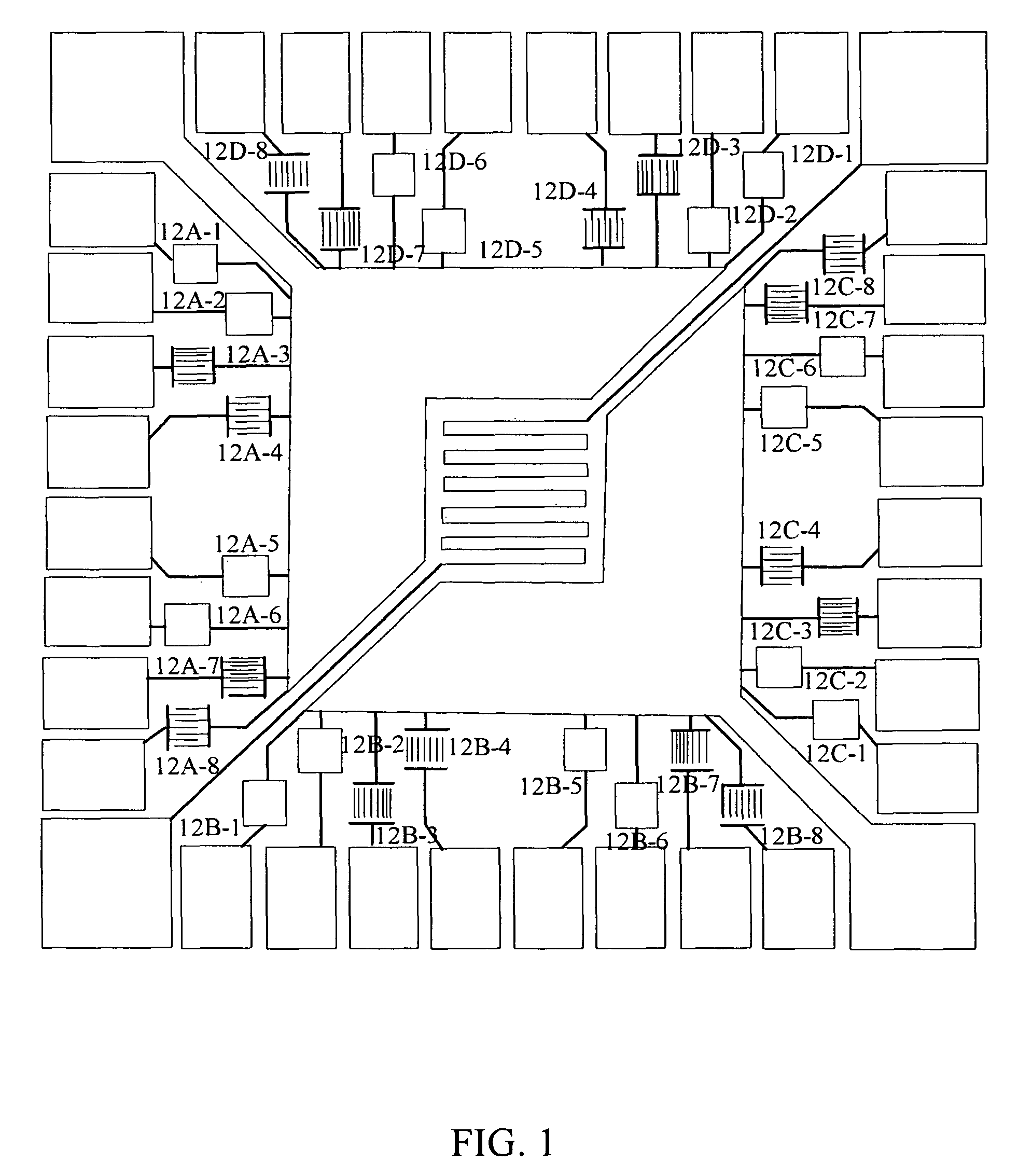
[0025]FIG. 1 illustrates a nanosensor 11, constructed according to an embodiment of the invention, including 32 interdigitated electrode fingers (“IDEFs”), 12A-1 through 12D-8, connected to first and second voltage sources, with a controllable voltage difference. In FIG. 1, a 1 cm×1 cm chip with Q sensing elements and SWCNTs bridging the gaps between adjacent IDEFs (Q=2-32). Each IDE is fabricated using conventional photolithography with a nominal finger width of 10 μm and gap sizes d=8, 12, 25 and 50 μm, or any other desired set of gap sizes. The fingers and contact pads are thermally evaporated Ti (20 nm thickness) and Pt (200 nm thickness) on a layer of SiO2, thermally grown on a silicon substrate. The sensing material is bulk-produced SWCNTs from a HiPCo process (Rice University.), purified to remove amorphous carbon and metal impurities according to a procedure described in the literature. The purified SWCNTs are dispersed in a selected solvent, such as dimethyl formamide, to c...


PUM


Abstract

A method and system for evaluating status and response of a mineral-producing field (e.g., oil and / or gas) by monitoring selected chemical and physical properties in or adjacent to a wellsite headspace. Nanotechnology sensors and other sensors are provided for one or more underground (fluid) mineral-producing wellsites to determine presence / absence of each of two or more target molecules in the fluid, relative humidity, temperature and / or fluid pressure adjacent to the wellsite and flow direction and flow velocity for the fluid. A nanosensor measures an electrical parameter value and estimates a corresponding environmental parameter value, such as water content or hydrocarbon content. The system is small enough to be located down-hole in each mineral-producing horizon for the wellsite.

Description

RELATION TO OTHER APPLICATIONS[0001]This application is a Continuation In Part of U.S. Ser. No. 11 / 178,079, filed 8 Jul. 2005, and of U.S. Ser. No. 11 / 416,505, filed 28 Apr. 2006.ORIGIN OF THE INVENTION[0002]This invention was made by one or more employees of the U.S. government. The U.S. government has the right to make, use and / or sell the invention described herein without payment of compensation, including but not limited to payment of royalties.FIELD OF THE INVENTION[0003]This invention relates to use of nanotechnology-based chemical sensors to evaluate chemical and physical parameters associated with oil or gas well exploration, development and operation.BACKGROUND OF THE INVENTION[0004]Current mechanical, electromagnetic or optical sensor technologies are relatively low-tech and passive, and do not acquire data at sufficient distances to permit reservoir managers to fully comprehend the chemical composition, volume and dynamics of the petroleum in a given reservoir. The most ...

Claims


Application Information

Patent Timeline
IPC IPC(8): G01N33/24G01N27/06G01N25/00G01N7/00G01N27/04
CPCE21B47/06E21B47/10G01V9/00Y10S977/957
Inventor LI, JINGMEYYAPPAN, MEYYA
Owner NASA
Why Eureka
Try Eureka