Tensioning device for extending a threaded bolt

a technology of extending device and threaded bolt, which is applied in the direction of threaded fasteners, load-modified fasteners, screws, etc., can solve the problem of only being able to set into operation

Inactive Publication Date: 2014-01-23
HOHMANN JORG +1
View PDF8 Cites 12 Cited by
  • Summary
  • Abstract
  • Description
  • Claims
  • Application Information

AI Technical Summary

Benefits of technology

[0014]For a compact structure, it is proposed that the pin is arranged in a longitudinal guide in the exchange socket. This has the additional advantage that when the exchange socket is replaced, the pin is also exchanged at the same time. This is because the two are matched to one another in terms of their geometric dimensions and to the threaded bolt to be tensioned.
[0015]According to a further configuration, the pin is formed in a radially widened manner at its lower pin end compared with the pin cross section. As a result of this radial widened section, the contact between the pin and the bolt to be tensioned always takes place in a single plane, specifically in the plane of the end face of the bolt and thus in that plane as far as which the external thread, available for the tensioning process, of the bolt usually extends, This measure makes it possible to assess the actual length of the thread engagement even in cases in which imprecise evaluation results would otherwise arise in the evaluation and control unit, for instance because the bolt has a central thread depression and the narrow end of the pin is supported in the latter and not on the actual end face of the threaded bolt.

Problems solved by technology

Rather, setting into operation is only possible after the evaluation and control unit has in principle enabled the hydraulic supply.

Method used


Image

  • Tensioning device for extending a threaded bolt
  • Tensioning device for extending a threaded bolt
  • Tensioning device for extending a threaded bolt

Examples


Embodiment Construction

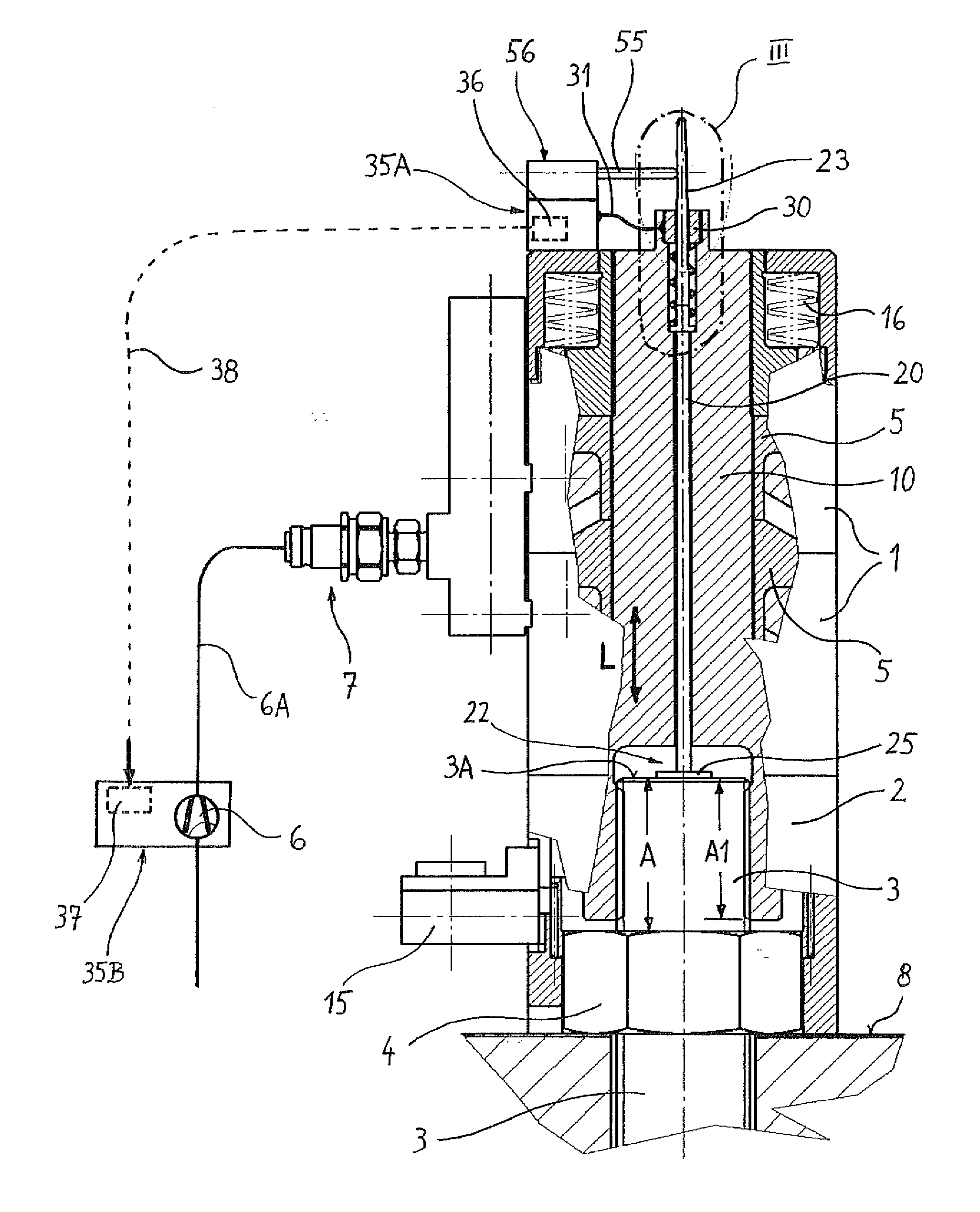
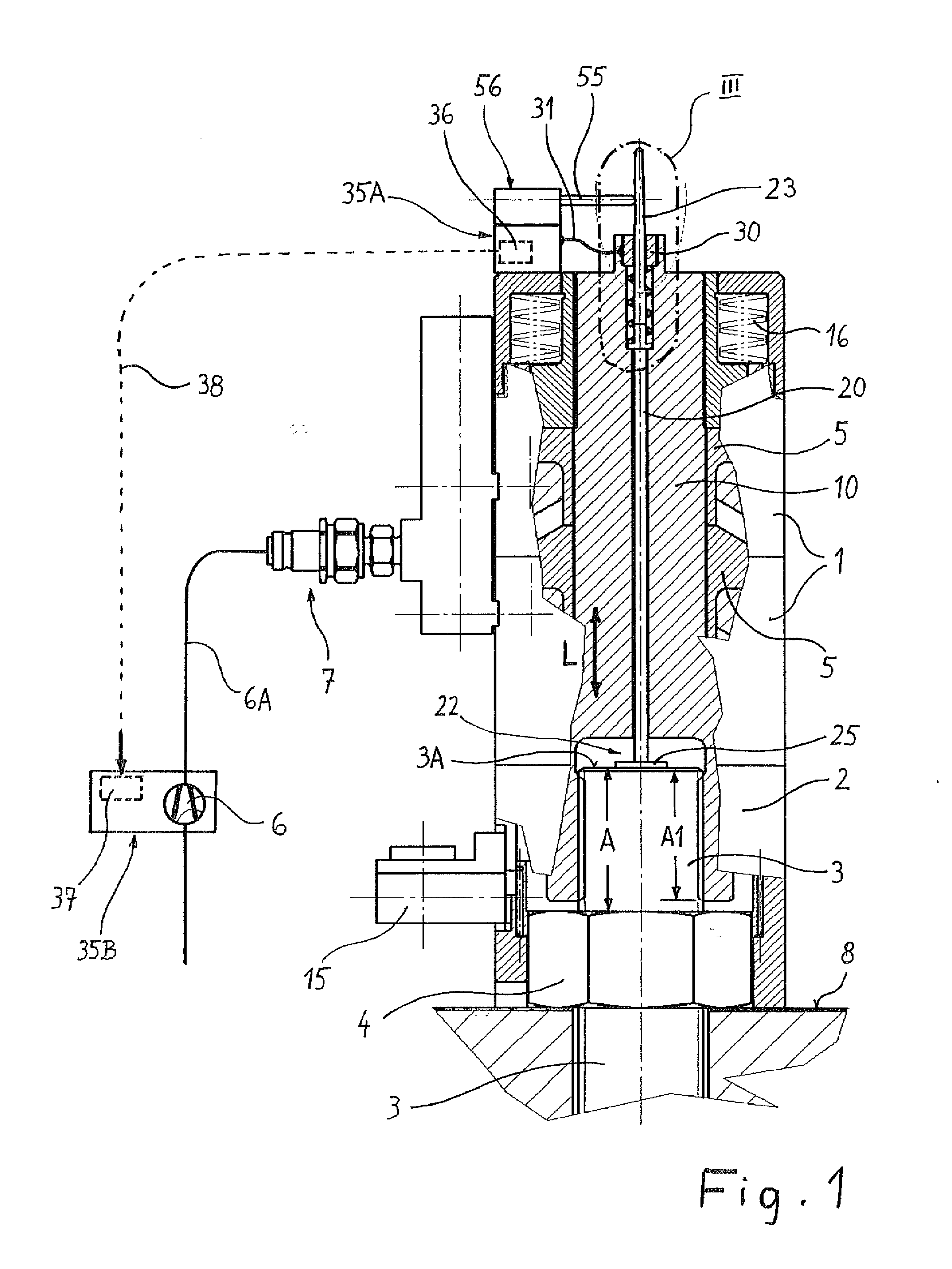
[0022]The hydraulically operated tensioning device serves to tighten and optionally also to release highly stressed screw connections. The tensioning device has the task of applying a predetermined pre-tensioning force onto the threaded bolt 3 for a certain amount of time in the longitudinal direction of the bolt, in order to create the possibility of tightening or retightening in a torque-free manner the nut 4, screwed onto the threaded bolt 3, of the screw connection. For this purpose, an exchange socket of the tensioning device which is described in more detail in the following text is screwed onto the thread, protruding beyond the nut 4, of the threaded bolt 3 and subsequently put under hydraulic tension, as a result of which the threaded bolt 3 is extended in the longitudinal direction.

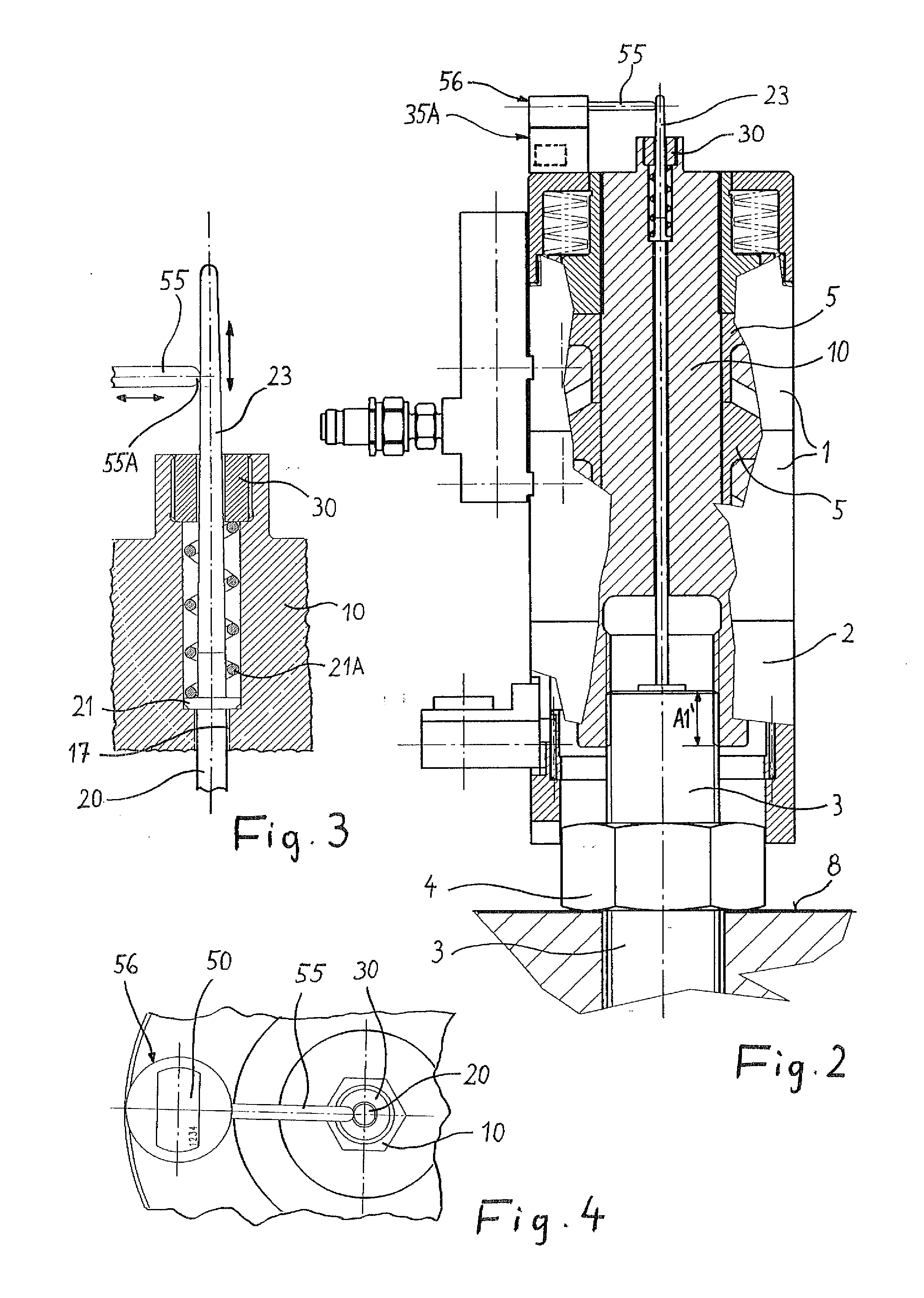
[0023]The screw-in depth of the threaded bolt is limited by the length, which is available as a bolt projection above the nut 4, of the threaded section A. The screw-in depth available should be ...


PUM


Abstract

A tensioning device for extending a threaded bolt by tensioning the threaded end section thereof is connectable to a hydraulic supply. The tensioning device has a supporting tube surrounding the threaded end section. A cylinder is arranged in continuation of the supporting tube and s piston is arranged in the cylinder and movable in longitudinal direction of the cylinder. An exchange socket is screwable to the threaded end section and configured to be carried along axially by the piston. A pin is movably arranged in the longitudinal direction and has a pin body with a first pin end supported in the longitudinal direction against the threaded end section of the threaded bolt. A sensing device senses a position of the pin in the longitudinal direction. An evaluation and control unit connected to the sensing device is acting on the hydraulic supply to enable the hydraulic supply.

Description

BACKGROUND OF THE INVENTION[0001]The invention relates to a tensioning device for extending a threaded bolt by way of tension on the threaded end section thereof, having a supporting tube surrounding the threaded end section, a cylinder which is arranged in continuation of the supporting tube and has at least one piston that is movable in the longitudinal direction therein and is connectable to a hydraulic supply, an exchange socket which is screwable to the threaded end section and is configured such that it can be carried along axially by the piston, and a pin which is arranged so as to be movable in the longitudinal direction and the pin end of which is supportable in the longitudinal direction against that end of the threaded bolt that has the threaded end section.[0002]A hydraulically operating bolt tensioning device having these features is known from U.S. 2011 / 0271798 A1. The tensioning device has measures for monitoring the thread projection, i.e. the length of the threaded ...

Claims


Application Information

Patent Timeline
Patent Type & Authority Applications(United States)
IPC IPC(8): B23P19/06
CPCB23P19/067B25B29/02F16B31/025F16B31/043
Inventor HOHMANN, JORGHOHMANN, FRANK
Owner HOHMANN JORG
Why Eureka
Try Eureka