
Automated storage and retrieval system for storing biological or chemical samples at ultra-low temperatures

a biological or chemical sample and automatic storage technology, applied in the field of automatic storage and retrieval systems for ultra-low temperature freezers, can solve the problems of system, robot and other components of the retrieval mechanism, system malfunction, and normal time-consuming defrosting procedure, so as to reduce the relative humidity within the compartment, improve reliability, and reduce the risk of moisture flow

Active Publication Date: 2011-01-04
HAMILTON STORAGE TECH
View PDF53 Cites 40 Cited by
  • Summary
  • Abstract
  • Description
  • Claims
  • Application Information

AI Technical Summary

Benefits of technology

The system reduces the need for frequent defrosting, minimizes moisture and heat ingress, and improves the reliability of the retrieval process by maintaining a controlled environment, thus extending the lifespan of components and protecting samples from premature thawing.

Problems solved by technology

Although there are a wide variety of manufacturers for freezer systems that are capable of cooling the storage compartment to an ultra-low temperature of, for example −80° C., the cooling process with some freezer systems is not particularly efficient.
Excessive frost can cause the system, and in particular the robot and the other components of the retrieval mechanism, to malfunction.
The defrosting procedure, however, is normally time-consuming.
Not only is the defrosting procedure quite time-consuming, but it can also lead to premature wear of system components, for example, robotic bearings or other components.
While a significant amount of moisture in current day systems is allowed into the ultra-low temperature freezer compartment through the access module when sample storage containers are introduced or retrieved, moisture and heat can also leak into the insulated, ultra-low temperature freezer compartment at any location where the freezer wall is breached.
For example, openings to pass a mechanical drive shaft through the freezer wall even if the opening is sealed can provide an opportunity for leakage, especially after the seal is worn.
This can lead to distortion problems during installation because of material shrinkage due to the ultra-low temperatures.
It should be noted that the placement of the reach arm or interchange mechanism must be accurate, especially with respect to the rotational accuracy, otherwise the system may malfunction and could possibly cause loss of samples.
Therefore, it has not been uncommon for technicians to spend significant time and effort accounting for thermal distortions during system set-up.
However, this design requires an active seal between the cylindrical base and the floor of the freezer which can at times be somewhat difficult to achieve and can become a source of wear.
Again, although the penetrating drive shaft is sealed, the breaching of the freezer wall provides an opportunity for heat and / or moisture to leak into the ultra-low temperature freezer compartment.
An issue also arises when it is desired to retrieve less than all of the storage tubes from a stored sample container, which is more often the case than not in these applications.
It is not desirable to remove the entire container from the system.
The removal procedure allows for the ingress of moisture in to the ultra-low temperature storage compartment, and also threatens that the other samples held in the same container will be thawed at least partially when removed from the system even if temporarily.
While tube picking mechanisms are generally known in the art, the environment within the ultra-low temperature freezer compartment is typically too cold to ensure reliable operation of conventional tube picking mechanisms.

Method used


Image

  • Automated storage and retrieval system for storing biological or chemical samples at ultra-low temperatures
  • Automated storage and retrieval system for storing biological or chemical samples at ultra-low temperatures
  • Automated storage and retrieval system for storing biological or chemical samples at ultra-low temperatures

Examples


Embodiment Construction

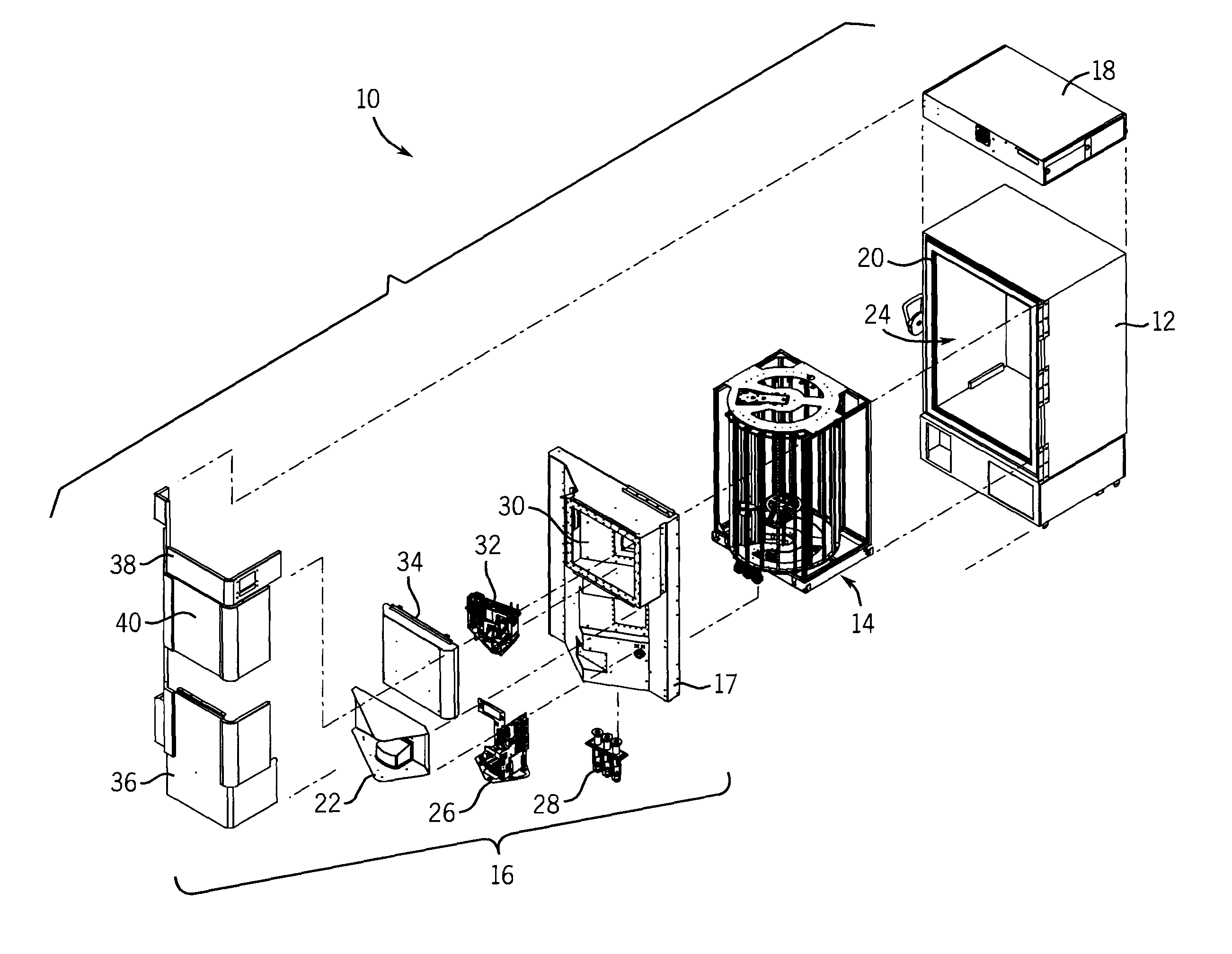
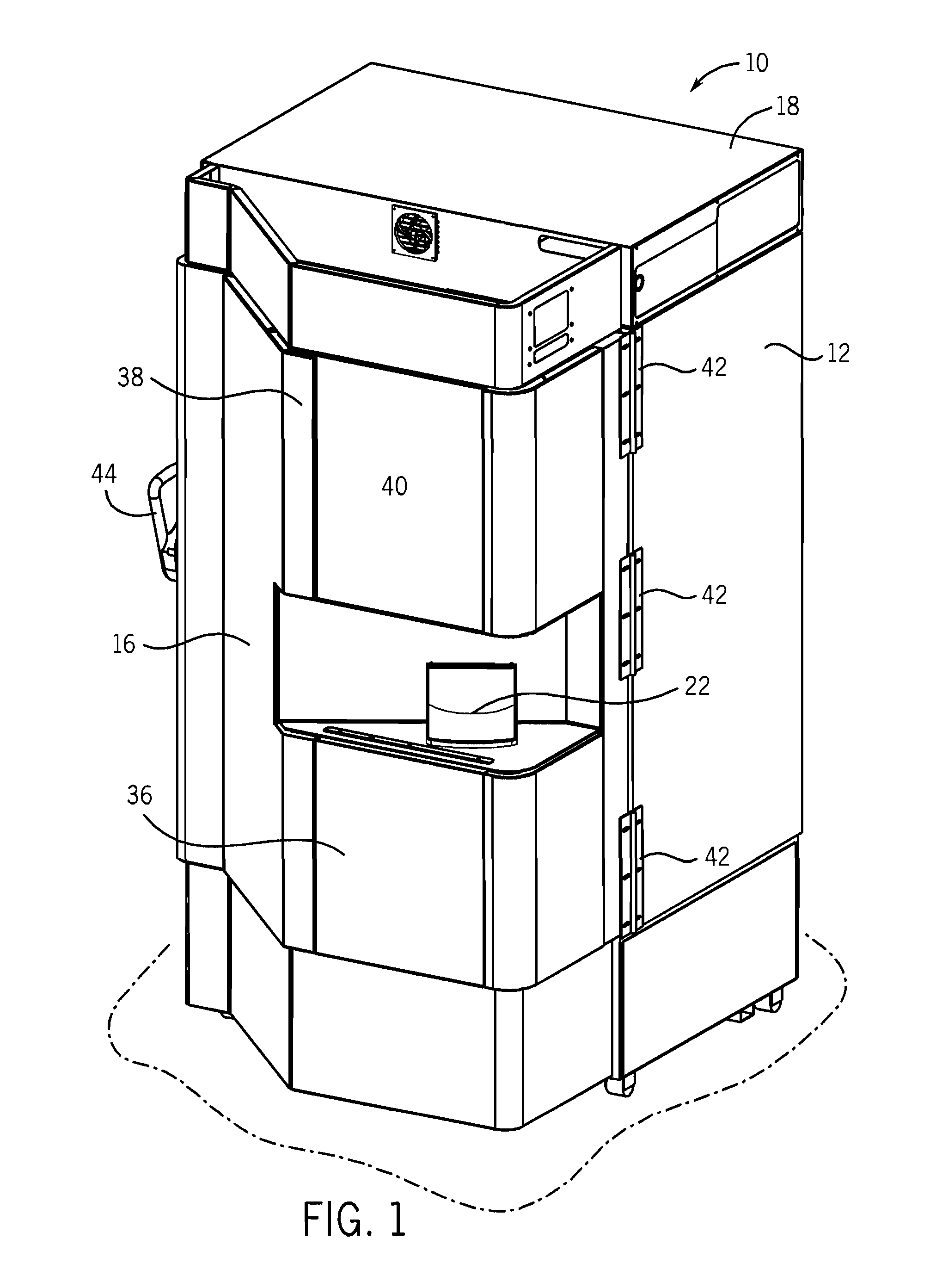
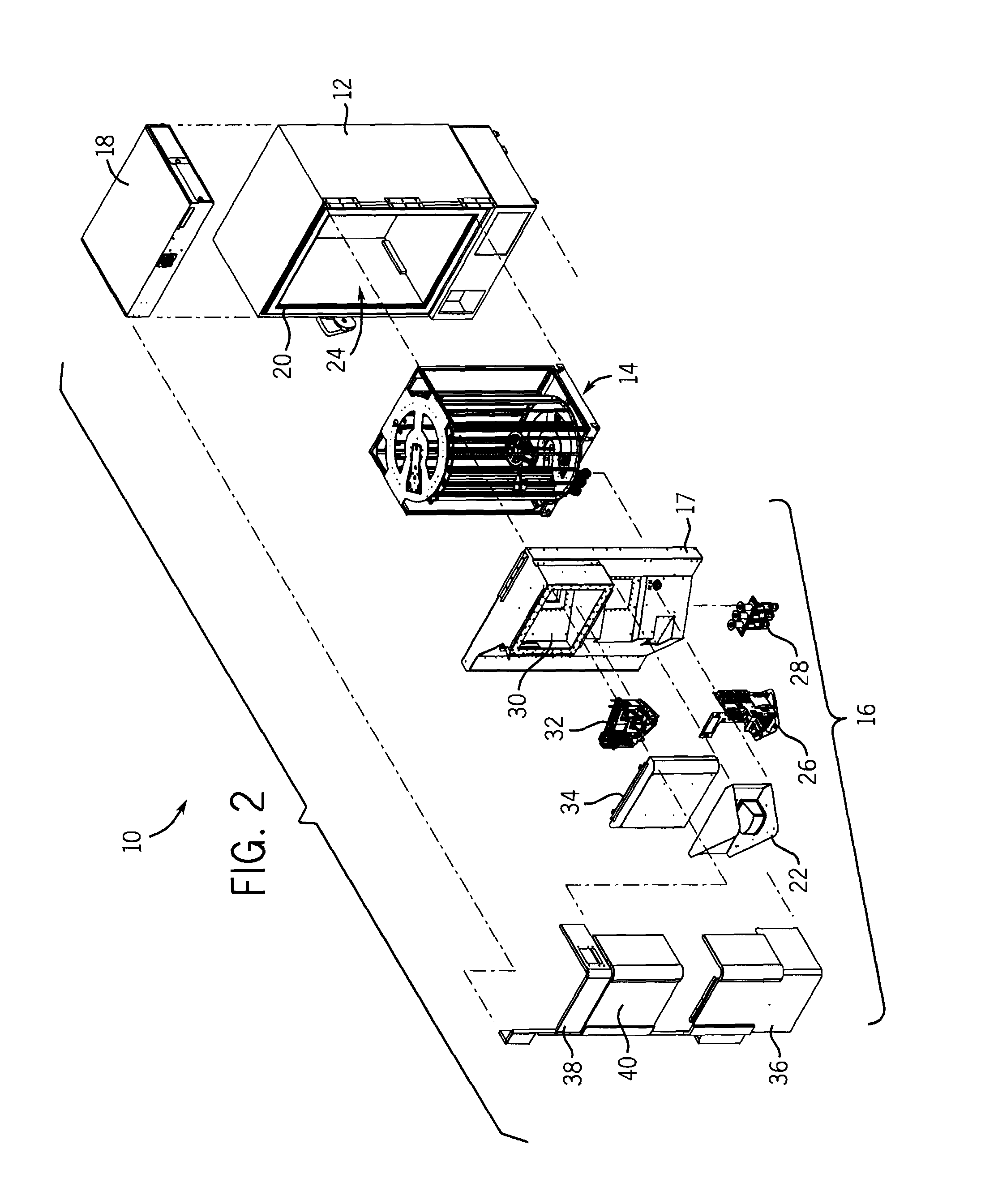
[0031]The Figures illustrate various aspects of a preferred embodiment of the invention. Referring to FIGS. 1 and 2, an automated storage and retrieval system 10 is configured to store sample storage containers, such as microtiter plates, racks for holding sealed storage tubes, or reservoirs at ultra-low temperatures. As mentioned, the system 10 is preferably designed to store SBS footprint compatible storage containers. The system 10 generally comprises a freezer body 12 for a standard ultra-low temperature freezer, an internal storage rack and robot assembly 14, a custom insulated door 16, and an electrical box 18. The preferred freezer body 12 is an upright −86° C. freezer body, purchased from Thermo Scientific, the Forma 907 Series, which is designed for ultra-low temperature storage for pharmaceutical, biotech and blood bank applications. These commercially available freezers typically come with installed racks, although these racks are not used in the present invention. In the...


PUM


Abstract

An automated storage and retrieval system stores containers, typically containing biological or chemical samples, at ultra-low temperatures, i.e., from about −50° C. to about −90° C., preferably about −80° C. under normal operating conditions. Dry gas air flows are used to reduce moisture and the consequential frost within the freezer compartment. A custom insulated door is provided with an access module and a tube picking compartment as well as servo motors for controlling a robot within the ultra-low temperature freezer compartment. The robot automatically places sample storage containers in stationary storage racks within the freezer compartment. Magnetic couplings are used to transmit mechanical power from outside of the freezer compartment to the robot inside of the freezer compartment. The robot has a simplified mechanical configuration. The custom door can be readily attached to standard freezer bodies.

Description

FIELD OF THE INVENTION[0001]The invention relates to automated storage and retrieval systems for ultra-low temperature freezers used primarily to store biological or chemical samples.BACKGROUND OF THE INVENTION[0002]Storage of biological and chemical samples is becoming widespread in the biotechnology and medical industries. To preserve many of these samples, the samples must be stored at or below freezing temperatures. Generally speaking, a regular freezer operates from −5° C. to −20° C., and an ultra-low temperature freezer operates from about −50° C. to about −90° C. (preferably at or about −80° C.) and a cryogenic freezer operates from about −140° C. to −196° C. (the boiling point of liquid nitrogen). The present invention is directed to ultra-low temperature freezers operating in the range of −50° C. to about −90° C., and preferably −80° C.[0003]U.S. Pat. No. 6,941,762 to Felder et al., as well as U.S. Pat. Nos. 6,688,123; 6,581,395; and 6,467,287 also by Felder et al., describ...

Claims


Application Information

Patent Timeline
Patent Type & Authority Patents(United States)
IPC IPC(8): F25D13/06F25D25/02
CPCF25D13/04F25D17/06F25D25/04G01N1/42F25D11/04F25D2317/0666F25D23/025B25J21/00
Inventor CLOUTIER, ROBERT P.WARHURST, JULIANZANDI, BEHROUZO'TOOLE, JAMESSOLBERG, HALVARD
Owner HAMILTON STORAGE TECH
Learn More