Eureka AIR delivers breakthrough ideas for toughest innovation challenges, trusted by R&D personnel around the world.

Transflective type liquid crystal display panel and method of fabricating the same

a liquid crystal display panel and transmitting-type technology, applied in optics, instruments, electrical equipment, etc., can solve the problems of large power consumption, narrow viewing angle, reflective-type liquid crystal display devices cannot display desired images in the dark surroundings,

Active Publication Date: 2010-12-28
LG DISPLAY CO LTD
View PDF5 Cites 4 Cited by
  • Summary
  • Abstract
  • Description
  • Claims
  • Application Information

AI Technical Summary

Benefits of technology

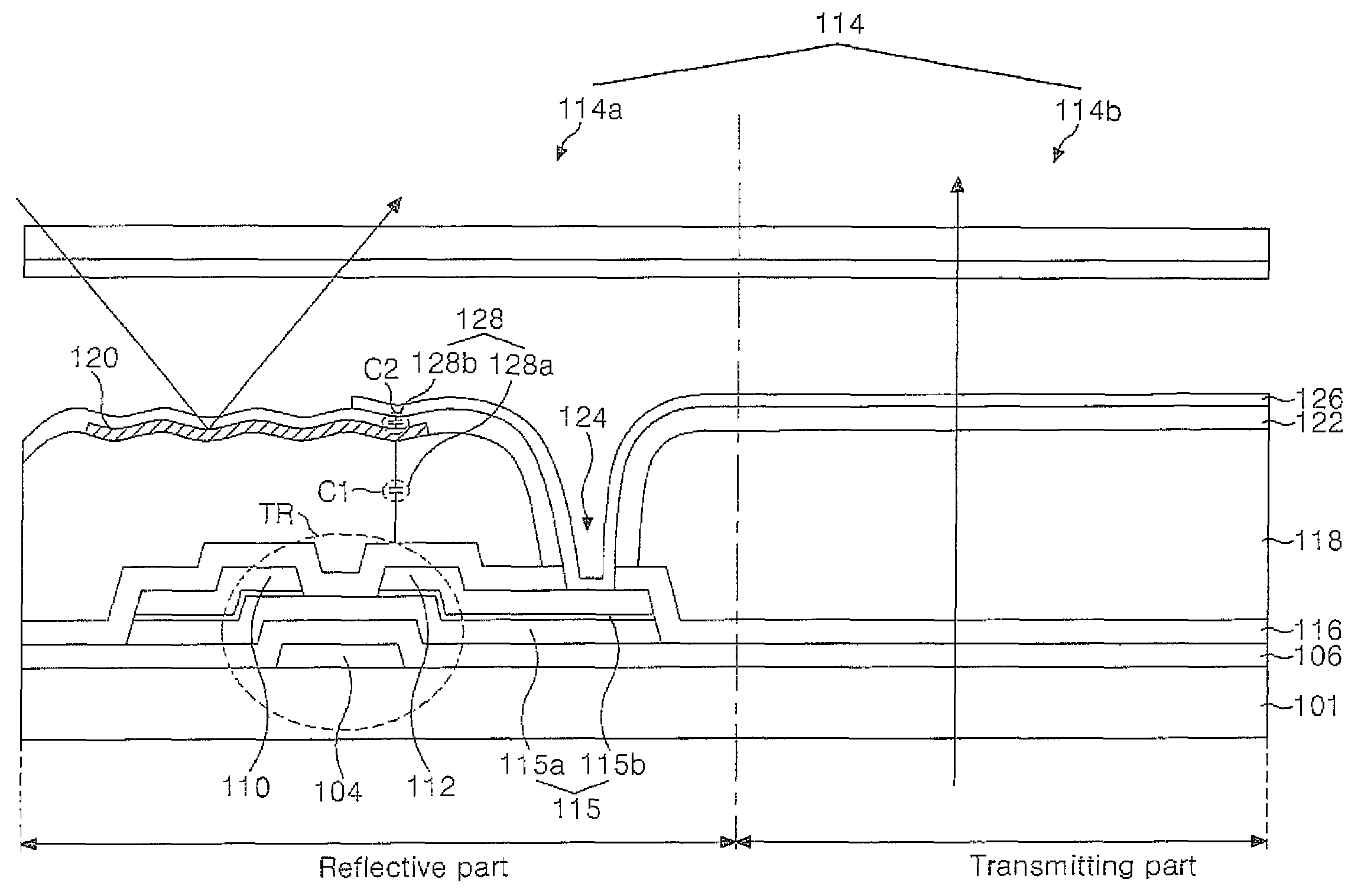
[0018]An object of the present invention is to provide a transflective type liquid crystal display panel which can form a uniform gray scale in a pixel region by matching up a reflective curve and a transmitting curve through a coupling capacitor in a reflective part of pixel region.

Problems solved by technology

This vertical electric field applying mode liquid crystal display device has an advantage of high aperture ratio, while it has a disadvantage of narrow viewing angle.
The transmitting type liquid crystal display device has a disadvantage of large power consumption.
The reflective type liquid crystal display device can not display desired images in the dark surroundings because the reflective type liquid crystal display device uses the ambient and surrounding light.
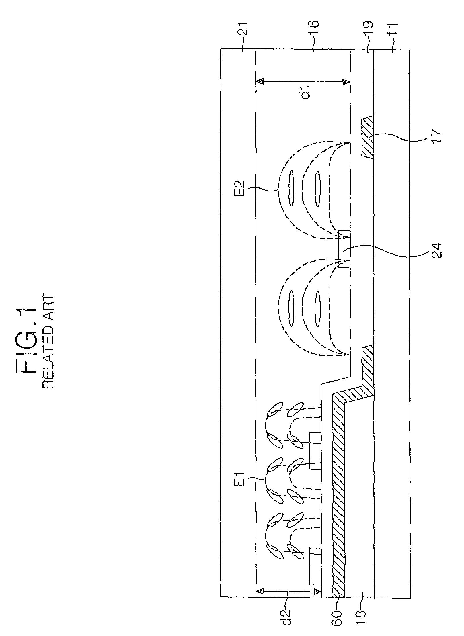
To form the dual cell gap structure for achievement of the uniform luminance property in the pixel region, it requires an additional step for forming the organic insulation film 60 in the reflective part, thereby causing the complicated process and low efficiency.
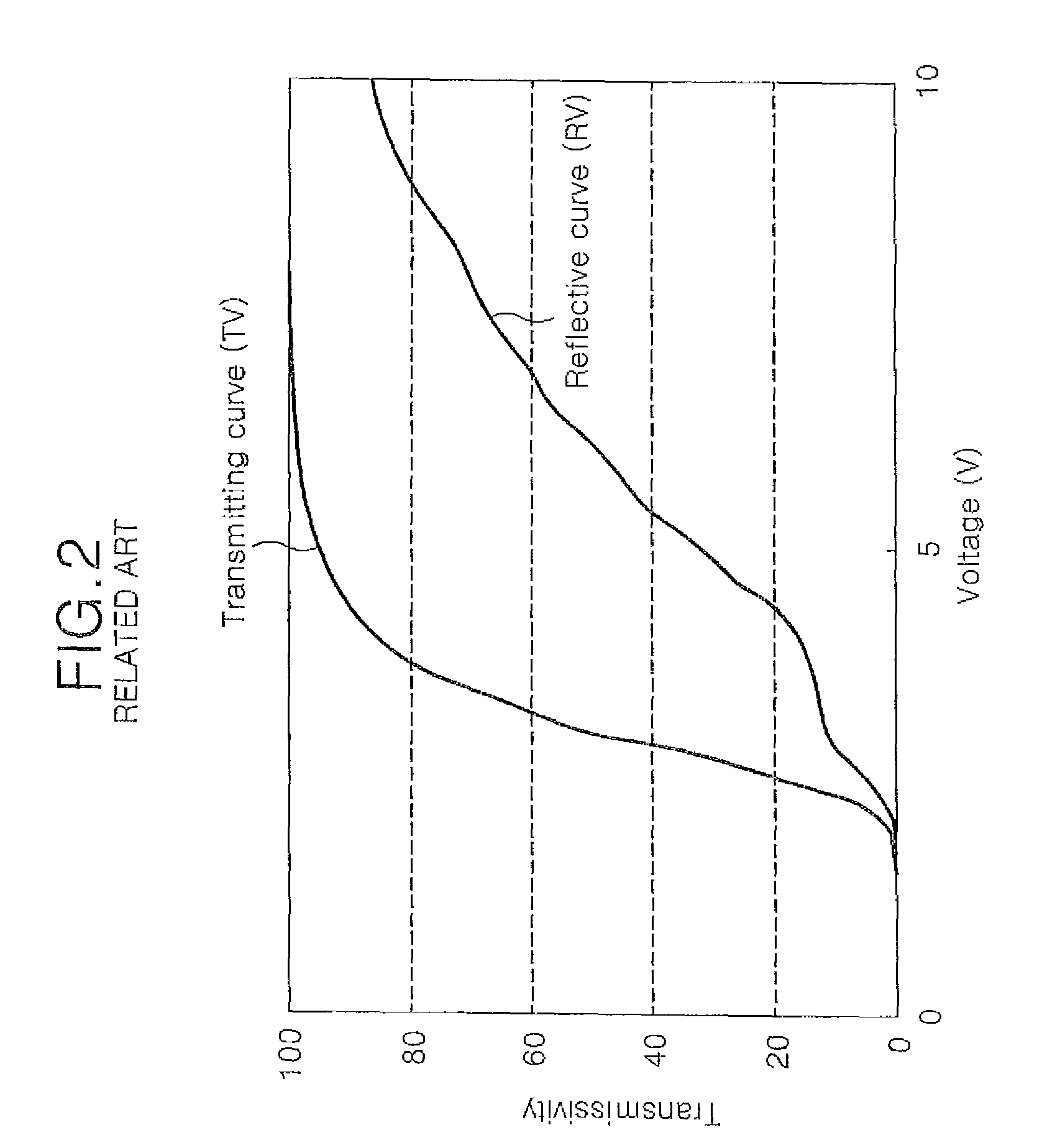
Accordingly, it is difficult to match up the reflective curve of reflective part and the transmitting curve of transmitting part in the related art transflective type liquid crystal display panel having the single cell gap structure, whereby the reflective part and the transmitting part for constituting the pixel region have the different gray scales.

Method used


Image

  • Transflective type liquid crystal display panel and method of fabricating the same
  • Transflective type liquid crystal display panel and method of fabricating the same
  • Transflective type liquid crystal display panel and method of fabricating the same

Examples


Embodiment Construction

[0036]Reference will now be made in detail to the preferred embodiments of the present invention, examples of which are illustrated in the accompanying drawings. Wherever possible, the same reference numbers will be used throughout the drawings to refer to the same or like parts.

[0037]Hereinafter, a transflective type liquid crystal display panel according to the present invention and a method of fabricating the same will be described with reference to the accompanying drawings.

[0038]A structure and operation of transflective type liquid crystal display panel according to the present invention will be explained with reference to FIGS. 3 and 4.

[0039]As shown in FIGS. 3 and 4, the transflective type liquid crystal display panel according to the present invention includes a gate line 102 on a substrate 102; a data line 108 crossing the gate line 102 to define a pixel region comprised of a transmitting part and a reflective part therein; a thin film transistor TR adjacent to a crossing ...


PUM

PropertyMeasurementUnit
voltageaaaaaaaaaa
electric capacityaaaaaaaaaa
organic insulationaaaaaaaaaa

Abstract

A transflective type liquid crystal display panel and a method of fabricating the same are discussed. The transflective type liquid crystal display panel according to an embodiment comprises a gate line on a substrate; a data line crossing the gate line to define a pixel region comprised of a transmitting part and a reflective part; a thin film transistor adjacent to a crossing of the gate and data lines; a first insulation film on a passivation film covering the thin film transistor; a reflective electrode in the transmitting part of the pixel region, for reflecting incident light; a pixel electrode formed on a second insulation film covering the reflective electrode, and connected to a drain electrode of the thin film transistor via a contact hole; and a coupling capacitor for matching a reflective curve of the reflective part with a transmitting curve of the transmitting part.

Description

[0001]This application claims the priority benefit of Korean Patent Application No. 10-2007-0029293 filed on Mar. 26, 2007, which is hereby incorporated by reference as if fully set forth herein.BACKGROUND OF THE INVENTION[0002]1. Field of the Invention[0003]Embodiments of the present invention relate to a transflective (transmitting-reflective) type liquid crystal display panel and a method of fabricating the same, and more particularly, to a transflective type liquid crystal display panel which can realize a uniform gray scale value in a pixel region by matching a reflective curve and a transmitting curve through a coupling capacitor in a reflective part of pixel region.[0004]2. Discussion of the Related Art[0005]Generally, a liquid crystal display (LCD) device displays images by controlling light transmittance of liquid crystal with the use of electric field. This liquid crystal display device is largely classified into a vertical electric field applying mode and a horizontal ele...

Claims


Application Information

Patent Timeline
Patent Type & Authority Patents(United States)
IPC IPC(8): G02F1/1335
CPCG02F1/133553G02F1/136213G02F2203/30G02F1/1335G02F1/136
Inventor KIM, HYUN HO
Owner LG DISPLAY CO LTD
Why Eureka
Eureka Blog
Learn More