
Precision sine vise

a machinist and precision technology, applied in the direction of mechanical means, instruments, manufacturing tools, etc., can solve the problems of reducing the overall precision of machining work pieces, affecting the machining accuracy of workpieces, and difficulty in clamping cylindrical workpieces parallel to the axial axis of the vise, so as to reduce backlash and chatter, and increase the proportional clamping force

Inactive Publication Date: 2010-12-21
STARK KATHLEEN DIANE
View PDF12 Cites 13 Cited by
  • Summary
  • Abstract
  • Description
  • Claims
  • Application Information

AI Technical Summary

Benefits of technology

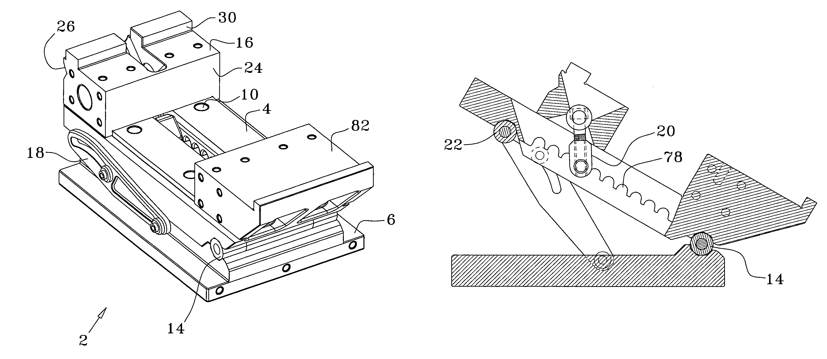
[0006]The general purpose of the present invention, which will be described subsequently in greater detail, is to provide a precision sine vise that is able to overcome the workpiece holding problems of the prior art sine vises and provide increased proportional clamping force, reduced backlash and chatter. It has many of the advantages mentioned heretofore and many novel features that result in a new and improved sine vise which is not anticipated, rendered obvious, suggested, or even implied by any of the prior art, either alone or in any combination thereof.
[0007]In accordance with the invention, an object of the present invention is to provide an improved sine vise capable of rapid, even clamping of work pieces.
[0008]It is another object of this invention to provide an improved sine vise capable of achieving a higher degree of precision when positioning a workpiece relative to a cutting tool.
[0010]It is still a further object of this invention to provide for an improved sine vise with a dual set of clamping faces so as to enable an enhanced range of jaw opening.

Problems solved by technology

Traditional vises have smooth faces on their jaw and the mating face on the vise body which makes clamping of cylindrical workpieces parallel to the axial axis of the vise difficult.
If it does have a V cut depression along the axial axis of the jaw to hold cylindrical work pieces, non cylindrical work pieces may be damaged when clamped.
Moreover, all of the aforementioned sources of movement in traditional sine vises act in unison to allow chatter, increase dimensional tolerances and decrease overall precision in the machining of work pieces.

Method used


Image

  • Precision sine vise
  • Precision sine vise
  • Precision sine vise

Examples


Embodiment Construction

[0041]There has thus been outlined, rather broadly, the more important features of the invention in order that the detailed description thereof that follows may be better understood and in order that the present contribution to the art may be better appreciated. There are, of course, additional features of the invention that will be described hereinafter and which will form the subject matter of the claims appended hereto. In this respect, before explaining at least one embodiment of the invention in detail, it is to be understood that the invention is not limited in its application to the details of construction and to the arrangements of the components set forth in the following description or illustrated in the drawings. The invention is capable of other embodiments and of being practiced and carried out in various ways. Also, it is to be understood that the phraseology and terminology employed herein are for the purpose of descriptions and should not be regarded as limiting.

[004...


PUM


Abstract

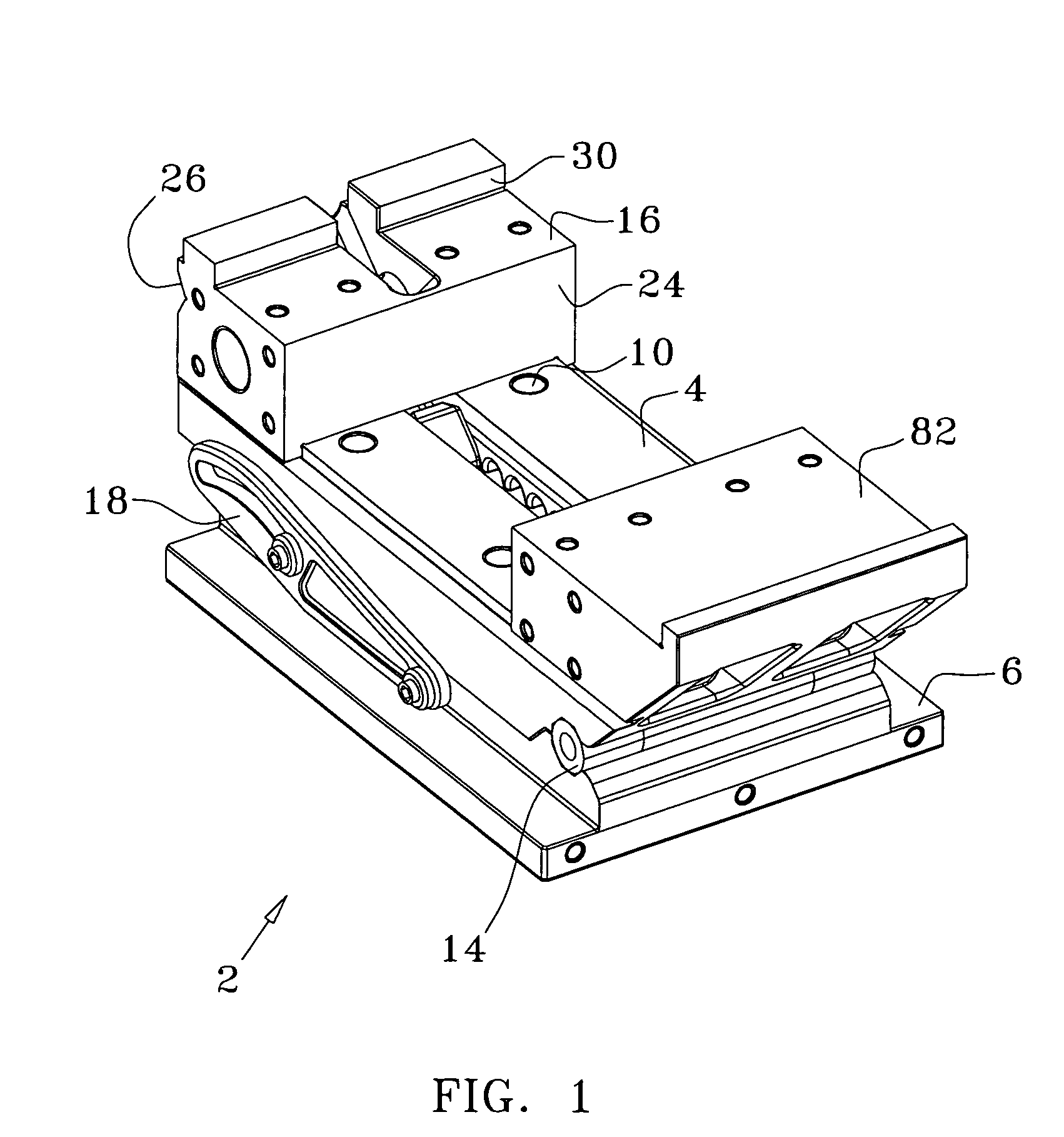
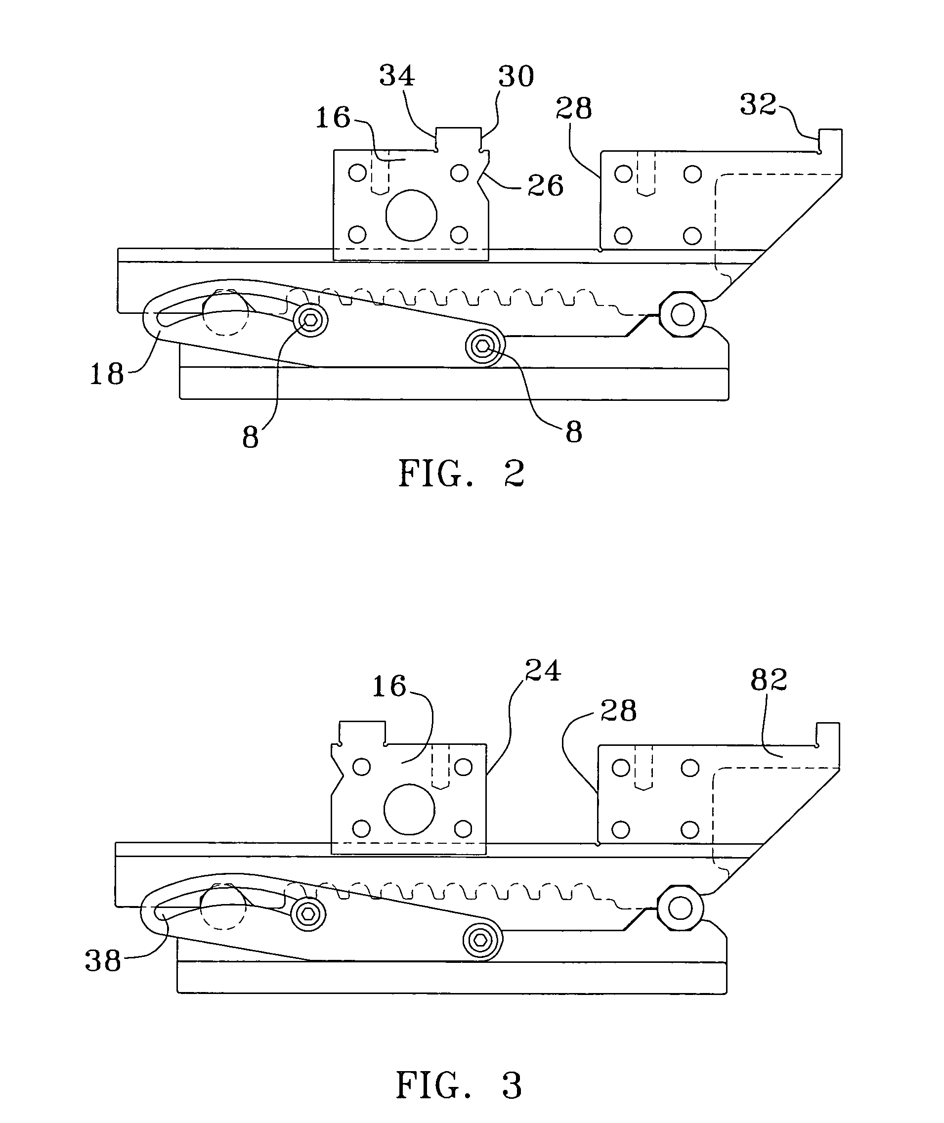
An improved sine vise that overcomes the deficiencies and limitations of conventional sine vises through the use of the following features: a circular sawtooth ratchet quick clamping system; a rotating dual jaw with one V cut depression face; a set of extended opening upper jaw lips; angle adjustment stays with counter rotating locking screws; a T shaped jaw clamping drawbar; a zero tolerance roll hinge; and a lipped vise base adapted for robust clamping to the cutting tool table with conventional T slot bolts and dogs.

Description

BACKGROUND OF THE INVENTION[0001]The present invention relates to a extremely sturdy and versatile machinist's sine vise adapted to provide a strong, quick adjusting clamp with enhanced directional stability that is capable of allowing the user to achieve extremely narrow dimensional and angular tolerances on clamped work pieces. More particularly, to a robust sine vise designed to provide for a “chatter free” machining environment.[0002]The level of accuracy and dimensional tolerance that can be achieved in the machining of a held workpiece by a rotating cutter is affected by several factors besides the capability of the machinist. Primarily these are: how tightly the workpiece can be held (clamping force) in the vise in all three dimensions; how much movement any vise component has relative to the other vise components (backlash); and how much movement the vise undergoes relative to the cutting tool's table when a cutting load is applied (chatter).[0003]Traditionally vises have ut...

Claims


Application Information

Patent Timeline
Patent Type & Authority Patents(United States)
IPC IPC(8): B23Q3/04
CPCB25B1/10B25B1/12B25B1/22B25B1/2405
Inventor STARK, MICHAEL CURT
Owner STARK KATHLEEN DIANE
Learn More