Method and apparatus for rapidly heating printing plates

a printing plate and rapid heating technology, applied in the field of ovens, can solve the problems of large space requirements, large space requirements of conveyor ovens, and further exasperation of space limitations, and achieve the effects of reducing space limitations, reducing heat loss, and reducing heat loss

Inactive Publication Date: 2010-11-09
KODAK CANADA ULC
View PDF19 Cites 4 Cited by
  • Summary
  • Abstract
  • Description
  • Claims
  • Application Information

AI Technical Summary

Benefits of technology

[0034]In accordance with this invention, a method and apparatus are disclosed for rapidly heating a planar printing plate as the plate moves through a heated air bearing. The heated air bearing comprises one or more curved heating surfaces. The planar printing plate is moved along a substantially curved path that is adjacent to at least one of the curved heating surfaces. While the plate is being moved along the substantially curved path, it is bent to substantially conform to the path. Each of the heating surfaces additionally comprises a plurality of openings that allow a flow of air to be conveyed towards the plate as the plate travels along the substantially curved path. Air is pressurized and heated and is conveyed through each of the heating surfaces. The planar printing plate is fed into heated air bearing and is bent by the flow of pressurized and heated air so as to conform and follow the contour of the substantially curved path. Alternatively, the printing plate can be bent or supported by additional mechanical means so as to conform and follow the substantially curved path through the air bearing. In either case, the portion of the planar printing plate moving along the substantially curved path is heated by the pressurized and heated flow of air. Since this portion of the plate has been bent to follow the curved path, the stiffness of this portion of the printing plate is increased considerably. This in turn helps to counter thermal distortion effects that occur from heating the plate from ambient temperature conditions and can cause the printing plate to distort and contact the heating surfaces, thus potentially damaging the plate. Therefore, this method of heating the printing plate allows for a smaller distance between the planar surface of the printing plate and any of the heated curved surfaces while minimizing potential damage to the plate itself. Consequently, the gap between two adjacent surfaces can also be made smaller. This smaller distance and gap, in turn increases the thermal heat transfer efficiency of the air bearing, thus promoting a rapid and energy efficient heating of the printing plate. A compact, energy efficient apparatus can be created to heat printing plates by this method. Such an apparatus additionally benefits from quick warm up times, and thus advantageously further reduces power consumption.

Problems solved by technology

Conveyor ovens typically need to be kept on all the time since their warm-up time is lengthy.
Conveyor ovens are typically very large in size and thus require substantial space requirements.
These space limitations are further exasperated when a processing line requires both pre-heat and post-bake capability.
Consistent and uniform oven temperatures have a significant effect on the quality of the processed plate, thus further increasing the complexity of conveyor ovens which includes a myriad of blowers, heating elements and extensive ductwork.
Ovens that comprise inductive heating (also known as RF heating) means or microwave heating means can offer instant warm up, but are expensive since they require many kilowatts of power at high frequencies.
In regular convection ovens most of the heated air bypasses the printing plate, therefore heat transfer efficiency is low.
However, one disadvantage of an air-bearing oven is that that the heat transfer efficiency is greatest when the planar surface of the printing plate is within a very small distance of the heated bearing pads.
A plate however typically distorts upon heating and this distortion can cause the plate to contact a heating pad when such small distances and gaps are employed.
This contact can cause damage to the plate, especially to its relatively delicate photopolymer or thermal photosensitive coating.
Such damage would be highly undesirable as it would likely lead to on-press printing artifacts.
This damage may be avoided by increasing the air bearing distance or gap, but at a cost of reduced heat transfer efficiency.
Needless to say, any contact may result in damage to the exposed or imaged coating, ultimately resulting in undesired on-press printing artifacts.

Method used


Image

  • Method and apparatus for rapidly heating printing plates
  • Method and apparatus for rapidly heating printing plates
  • Method and apparatus for rapidly heating printing plates

Examples


Embodiment Construction

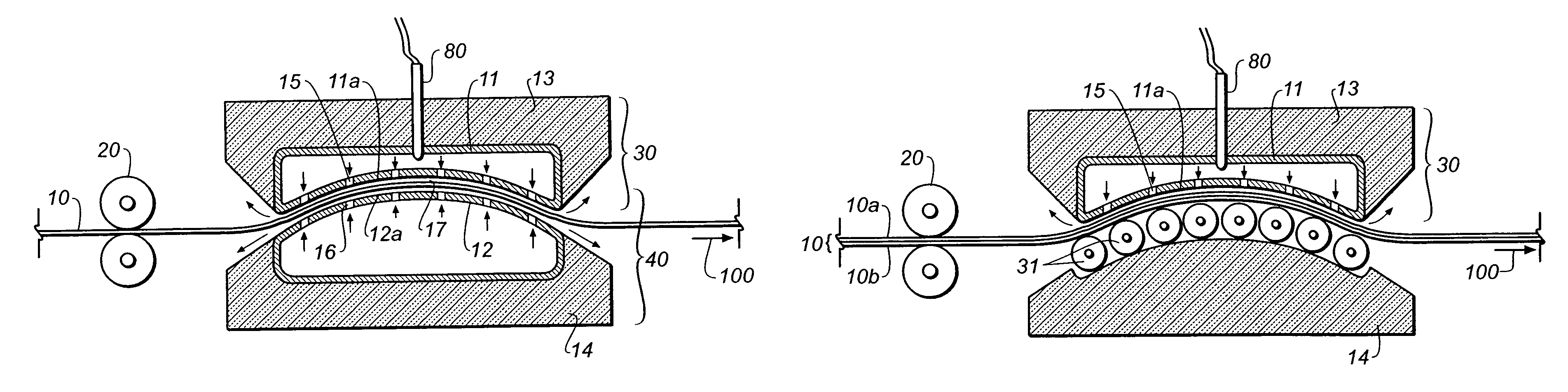
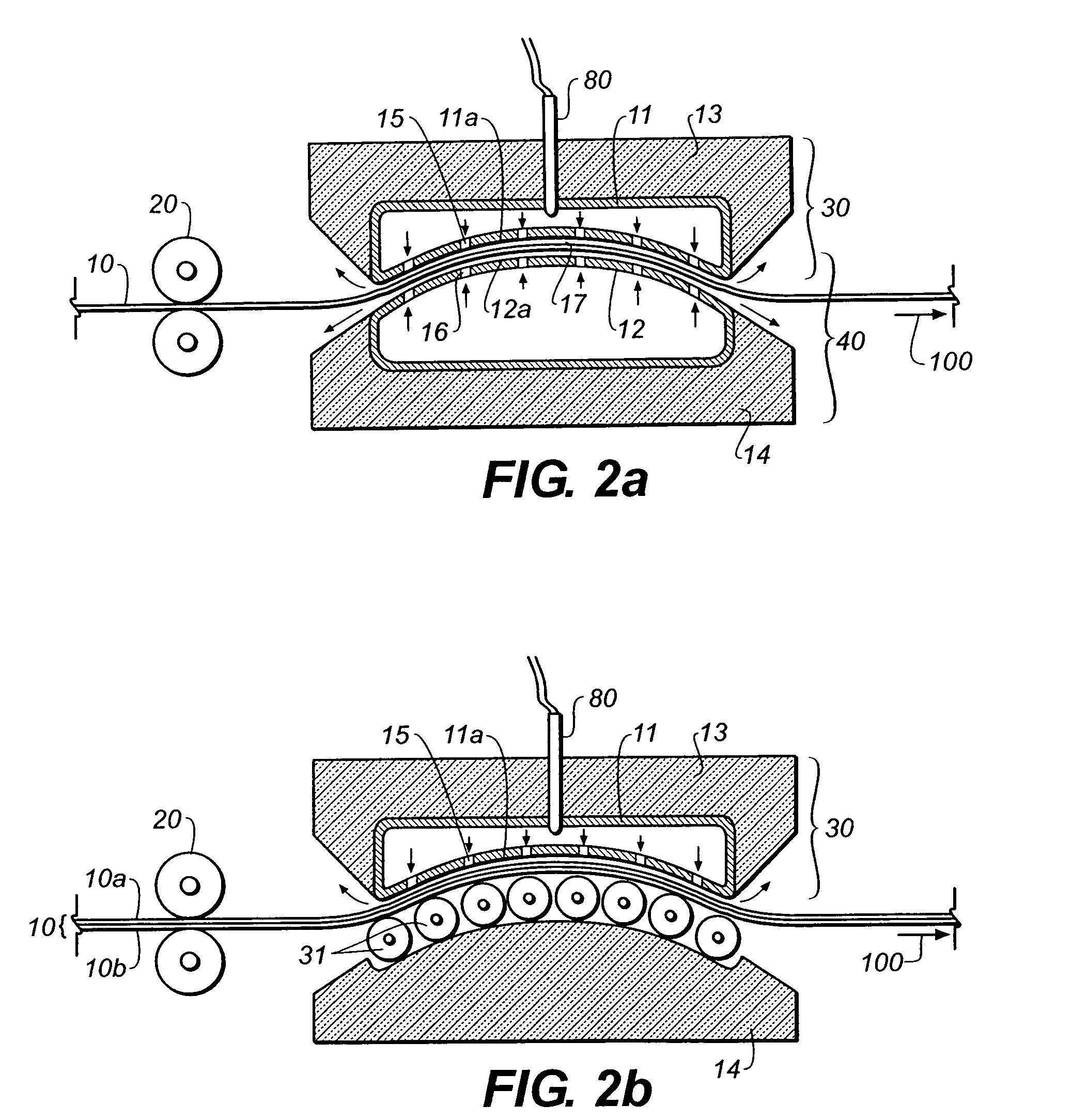
[0043]Regardless of whether a given printing plate is a “conventional” plate that is exposed through a film mask or a “digital” plate that is imaged by a CTP imager, the printing plate typically comprises a polyester or metal substrate. Further, aluminum and aluminum alloys are the preferred choice of most metal-based printing plates. Both polyester and metal printing plates are susceptible to thermal changes. Additionally, polyester is also susceptible to humidity changes. Both aluminum and polyester have coefficients of thermal expansion of approximately 20-23 μm / m / ° C. (or 20-23 parts per million (ppm) / ° C.). The coefficient of thermal of expansion is a material specific constant used to estimate the change in length or size that an object undergoes when heated or cooled from a known temperature. Required oven pre-heating temperatures are typically in range of from about 100 to about 250° C. above ambient conditions. As previously stated, the prior art has disclosed air bearing h...


PUM

PropertyMeasurementUnit
temperatureaaaaaaaaaa
poweraaaaaaaaaa
temperaturesaaaaaaaaaa

Abstract

Rapid heating of a lithographic printing plate is achieved by feeding the printing plate along a substantially curved path that is adjacent to one or more curved pads of an air bearing that is pressurized with heated air. The one or more curved pads are constructed such that the substantially curved path is curved with an axis of curvature substantially perpendicular to the feed direction of the printing plate. The plate is additionally elastically bent to follow and conform to the substantially curved path. The substantially curved path minimizes printing plate distortion during heating, and thus prevents the plate from being damaged from contact with any of the one or more curved pads. The one or more curved pads are also arranged to allow for exceptionally good heat transfer characteristics and thus more effective plate heating.

Description

CROSS-REFERENCE TO RELATED APPLICATION[0001]This application relates to provisional application 60 / 634,748, filed Dec. 10, 2004.FIELD OF THE INVENTION[0002]The invention pertains to the field of ovens and, in particular, to ovens for rapidly heating printing plates.BACKGROUND OF THE INVENTION[0003]Printing operations undertaken in an offset printing press typically utilize lithographic printing plates. These lithographic printing plates are produced in a separate process involving the exposure of an image onto a plate substrate that typically comprises a thin aluminum alloy suitably treated so as to be sensitive to light or heat radiation.[0004]One process of making a lithographic plate suitable for use on an offset printing press has been to employ a film mask. Exposing highly sensitive film media using a low power laser printer known as an “image-setter” typically produces this film mask. The film media is usually processed in some manner and is then placed in area contact with a ...

Claims


Application Information

Patent Timeline
Patent Type & Authority Patents(United States)
IPC IPC(8): F27B9/14F27B9/28
CPCB41C1/1083
Inventor GELBART, DANIEL
Owner KODAK CANADA ULC
Why Eureka
Try Eureka