
Fundus oculi observation device and fundus oculi image processing device

a technology of observation device and image processing device, which is applied in the field offundus oculi observation device and fundus oculi image processing device, can solve the problems of difficult setting, measurement error resulting from and inability to generate flares in observation images and photographed images, etc., and achieve the effect of accurately obtaining the magnification of the ocular optical system of an ey

Active Publication Date: 2010-11-09
KK TOPCON
View PDF10 Cites 9 Cited by
  • Summary
  • Abstract
  • Description
  • Claims
  • Application Information

AI Technical Summary

Benefits of technology

The present invention provides a fundus oculi observation device and fundus oculi image processing device that can accurately obtain the magnification of the ocular optical system of an eye. This is achieved by an image forming part that optically acquires data and forms a tomographic image of the fundus oculi, a storage that stores optical information representing the state of the ocular optical system, a calculator that calculates the magnification of the ocular optical system based on the optical information, and an analyzer that analyzes the tomographic image based on the magnification. This technology allows for more accurate and reliable observation and analysis of the fundus oculi.

Problems solved by technology

Consequently, generation of flare in observation images and photographed images is inhibited.
In this evaluation of the thickness of a layer of the fundus oculi, a measurement error resulting from the ocular optical system of an eye may occur.
Therefore, it has been difficult to set the positions of the radii m1, m2 and m3 from the center C of the optic papilla at proper positions, namely, accurately set.
However, since this method employs a standard value based on the eye model, it has been difficult to accurately obtain the magnification of the eye.
Therefore, it has been difficult to set the measurement lines M1, M2 and M3 at proper positions with respect to the eye.

Method used


Image

  • Fundus oculi observation device and fundus oculi image processing device
  • Fundus oculi observation device and fundus oculi image processing device
  • Fundus oculi observation device and fundus oculi image processing device

Examples


Embodiment Construction

[0062]An example of a preferred embodiment of a fundus oculi observation device and a fundus oculi image processing device according to the present invention will be described in detail referring to the drawings. Herein, the same components as the conventional ones shown in FIGS. 15 and 16 will be denoted by the same reference numerals used therein.

[Configuration of Device]

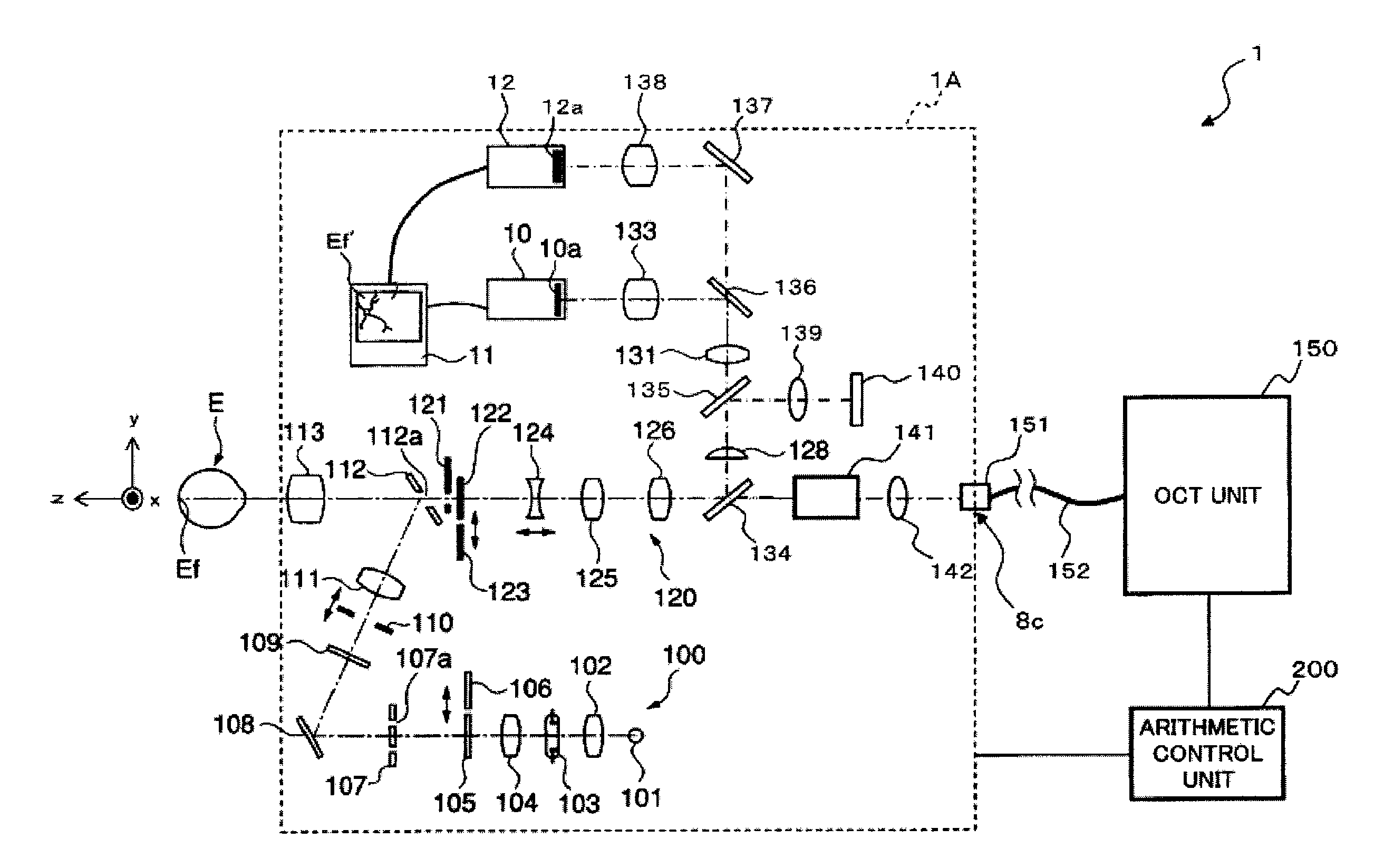
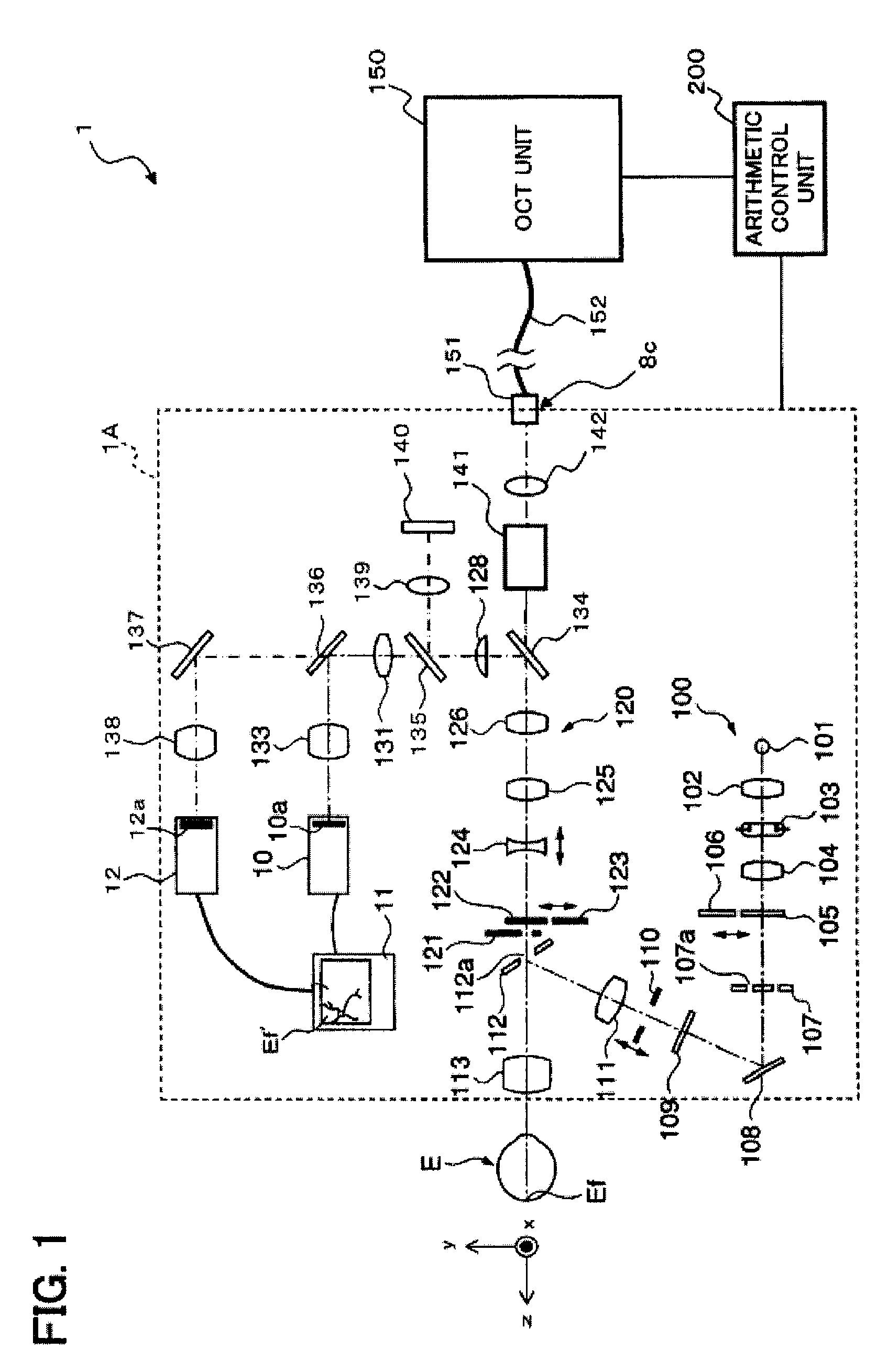
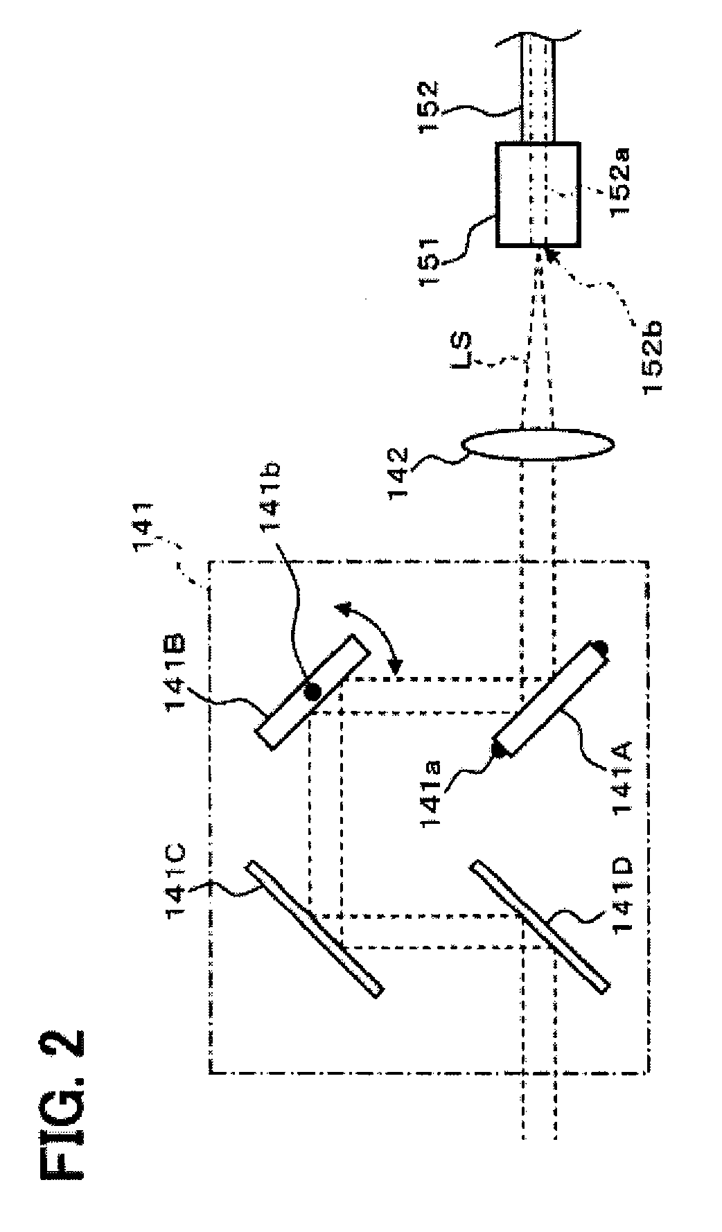
[0063]First, referring to FIGS. 1-7, the configuration of the fundus oculi observation device according to a first embodiment of the present invention will be described. FIG. 1 shows an example of the entire configuration of a fundus oculi observation device 1 according to the present embodiment. FIG. 2 shows an example of the configuration of a scanning unit 141 in a retinal camera unit 1A. FIG. 3 shows an example of the configuration of an OCT unit 150. FIG. 4 shows an example of the hardware configuration of an arithmetic control unit 200. FIG. 5 shows an example of the configuration of a control system of the ...


PUM


Abstract

A fundus oculi observation device comprises: an image forming part configured to optically acquire data and form a tomographic image of a fundus oculi of an eye; a storage configured to store optical information representing a state of an ocular optical system of the eye; a calculator configured to calculate a magnification of the ocular optical system, based on the optical information; and an analyzer configured to analyze the tomographic image, based on the magnification.

Description

BACKGROUND OF THE INVENTION[0001]1. Field of the Invention[0002]The present invention relates to a fundus oculi observation device for observing a fundus oculi, and a fundus oculi image processing device for processing a fundus oculi image.[0003]2. Description of the Related Art[0004]As a fundus oculi observation device, a retinal camera has been widely used conventionally. FIG. 15 shows an example of the appearance of a general retinal camera used conventionally. FIG. 16 shows an example of the configuration of an optical system internally accommodated in the retinal camera (refer to Japanese Unexamined Patent Application Publication No. 2004-350849, for example). Herein, “observation” includes at least a case of observing a photographed fundus oculi image (observation of a fundus oculi with a naked eye may be included).[0005]First, referring to FIG. 15, the appearance of a conventional retinal camera 1000 will be described. This retinal camera 1000 is provided with a platform 3 mo...

Claims


Application Information

Patent Timeline
Patent Type & Authority Patents(United States)
IPC IPC(8): A61B3/14
CPCA61B3/102G01B9/0203G01B9/02044G01B9/02091G01B9/02083G01B9/02089G01B2290/65
Inventor KIKAWA, TSUTOMUFUJIMURA, TAKASHIAOKI, HIROYUKISUEHIRO, JUNFUKUMA, YASUFUMI
Owner KK TOPCON
Learn More