
Processing method device and system to produce a focused image signal from an unfocused image

a processing method and image signal technology, applied in the field of digital imaging systems, can solve the problems of inefficient use of available light by pinhole cameras, negligible differences, and inability to form images, etc., and achieve the effects of convenient reconfiguration, high efficiency, and convenient manufacturability

Inactive Publication Date: 2010-11-02
COOPER ALLAN J
View PDF6 Cites 2 Cited by
  • Summary
  • Abstract
  • Description
  • Claims
  • Application Information

AI Technical Summary

Benefits of technology

This approach allows for high-speed, low-light, and high-resolution image acquisition in a compact form factor, reducing mechanical complexity and manufacturing sensitivity, while enabling efficient light use and easy reconfiguration for different applications.

Problems solved by technology

At large distances from the light source, however, this divergence becomes negligible.
A pinhole camera uses available light inefficiently.
Other light arriving at the barrier is absorbed by, or reflected from, the barrier and is thus unavailable for image formation.
Furthermore, the resolution of the image on the screen is limited by aperture size.
While refractive lens systems provide relatively high efficiency and resolution, they have significant disadvantages.
To some extent lens system thickness may be reduced by applying fresnel lenses, however use of a fresnel system implies other design constraints.
In addition, optical materials having desirable refractive characteristics may be relatively dense, resulting in correspondingly heavy focusing systems.

Method used


Image

  • Processing method device and system to produce a focused image signal from an unfocused image
  • Processing method device and system to produce a focused image signal from an unfocused image
  • Processing method device and system to produce a focused image signal from an unfocused image

Examples


Embodiment Construction

[0034]The present invention will be described as set forth in the exemplary embodiments illustrated in FIGS. 1-15. Other embodiments may be utilized and structural or functional changes may be made without departing from the spirit or scope of the present invention. Like items are referred to by like reference numerals.

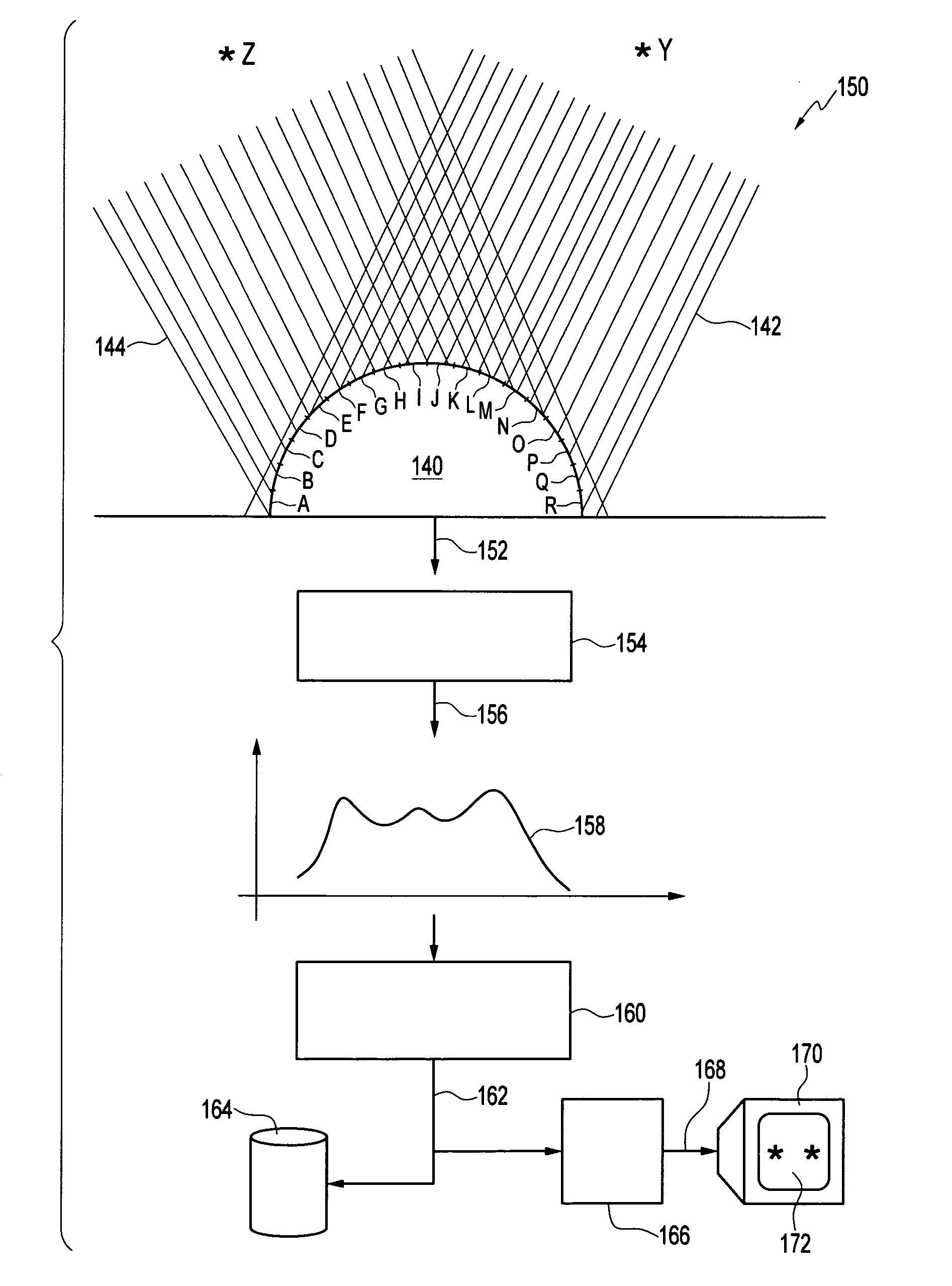
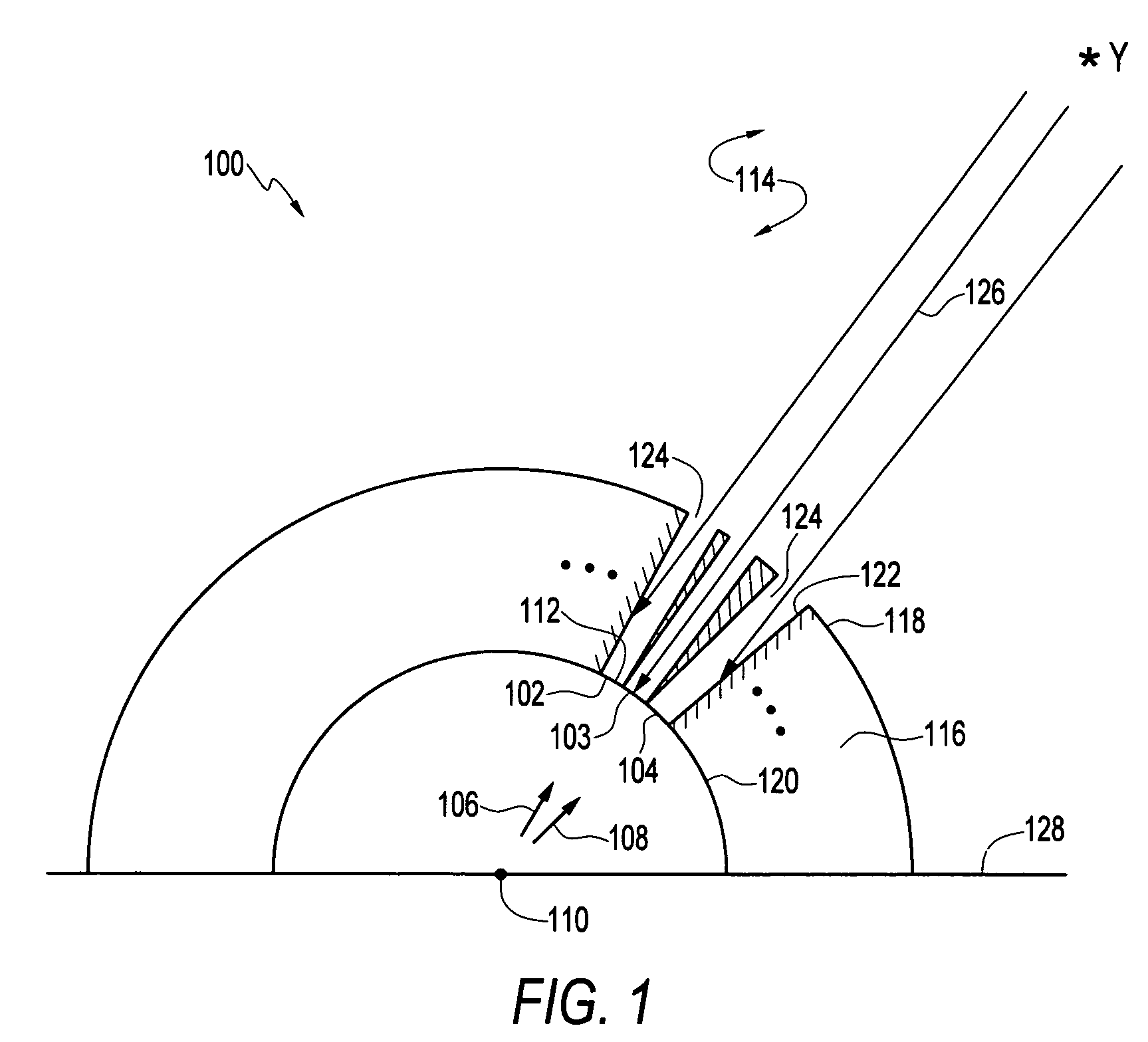
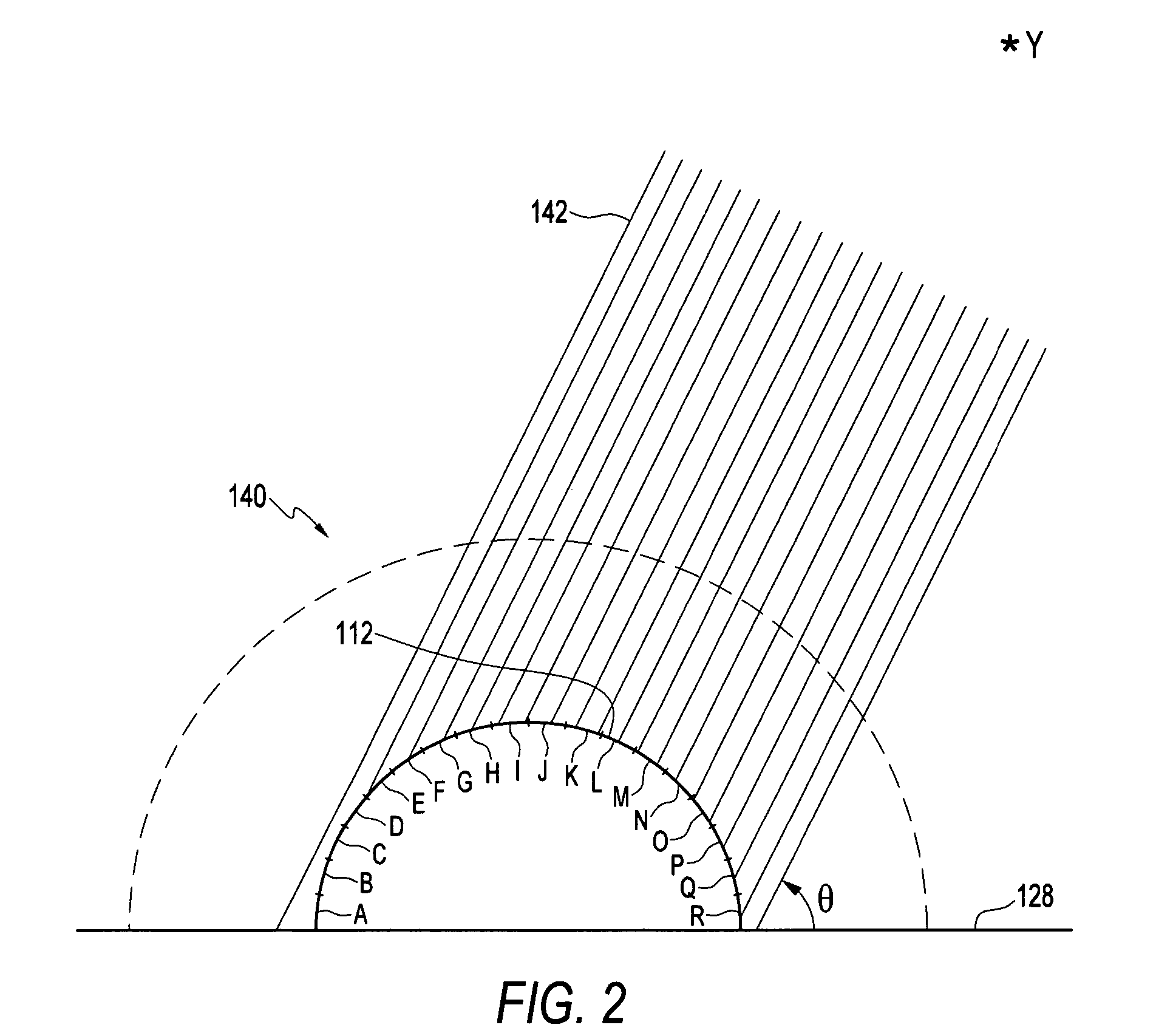
[0035]In a first aspect, the present invention relates to a digital imaging system adapted to receive an optical input signal from one or more remote active or passive light sources and produce an image output signal corresponding to the optical signal. The invention may include a display device adapted to display a visual image according to the image output signal, and may further include a storage device adapted to store the image output signal for display at another time. In one aspect, the invention includes a sensing system for sensing light intensity arriving from a plurality of directions with respect to the sensing system. According to one embodiment of the in...


PUM


Abstract

A method and apparatus are disclosed for forming an image signal by receiving a flux of photons at a convex photodetector such as a hemispherical photodetector. The convex photodetector includes a plurality of photosensors. Each photosensor has a different orientation with respect to a propagation vector of the flux of photons. The photosensors generate a respective plurality of intensity signals. Each of the intensity signals is related to the respective orientation of the photosensor that generates it. The intensity signals are received by a signal processor, such as a digital signal processor, which uses the intensity signals to compute an image signal related to the intensity signals and thereby produce a focused output image.

Description

CROSS REFERENCE TO RELATED APPLICATIONS[0001]The present application claims the benefit of U.S. provisional patent application Ser. No. 60 / 617,139, filed Oct. 8, 2004, the disclosure of which is herewith incorporated by reference in its entirety.FIELD OF THE INVENTION[0002]The present invention relates to imaging systems and more particularly to digital imaging systems.BACKGROUND OF THE INVENTION[0003]Conventional optical photographic and video cameras, telescopes and microscopes are used to display and / or record images. Such systems rely on reflective and refractive optical lenses. The refractive optical lenses serve to focus light within the systems. Typically, the lenses are made of glass or plastic, and exhibit fundamental characteristics substantially unchanged since the time of Galileo. Refractive optical lenses range in size from microscopic dimensions to meters across.[0004]A refractive lens focuses an image by directing to a particular point on a focal plane photons origina...

Claims


Application Information

Patent Timeline
Patent Type & Authority Patents(United States)
IPC IPC(8): H04N3/14H04N5/335H04N23/40H04N25/00
CPCH04N5/262H04N5/335H04N25/00H04N25/702
Inventor COOPER, ALLAN J.
Owner COOPER ALLAN J
Learn More