
Electrostatic spraying device

a technology of electrostatic spraying and spraying liquid, which is applied in the direction of positive displacement liquid engines, piston pumps, instruments, etc., can solve the problems of affecting the normal affecting the smooth operation of the device, so as to achieve easy dripping of liquid composition, easy handling of the device, and successful spraying

Active Publication Date: 2010-11-02
THE PROCTER & GAMBLE COMPANY +1
View PDF42 Cites 15 Cited by
  • Summary
  • Abstract
  • Description
  • Claims
  • Application Information

AI Technical Summary

Benefits of technology

"The present invention is an electrostatic spraying device that can spray liquid compositions successfully only through a simplified step of confirming that the liquid composition is ready for being immediately sprayed electrostatically. The device includes an actuator, a high voltage generator to provide a high voltage, a power source to activate the actuator and the high voltage generator, a reservoir to contain the supply of the liquid composition, and a dispensing unit. The device also includes a selector to select between a dripping mode and a spraying mode, a switch to activate the power source, and a housing to carry the actuator, the high voltage generator, the power source, the switch, and the selector. The spraying mode defines a mode in which the pump as well as the emitter electrode are simultaneously activated to dispense the liquid composition with the liquid composition being electrically charged prior to exiting the nozzle. The device also includes a lock position to prevent accidental operation, an indicator to confirm which mode is selected, and a control to monitor voltage output and cease activating the high voltage generator and the pump when voltage output exceeds a critical level. The technical effects of the invention include easy handling of the device, successful spraying, and safe operation."

Problems solved by technology

Thus, the absence of the confirmation might give uncertainty to the user whether or not the device operates normally.
This is cumbersome and therefore detracting from easy handling of the device.

Method used


Image

  • Electrostatic spraying device
  • Electrostatic spraying device
  • Electrostatic spraying device

Examples


Embodiment Construction

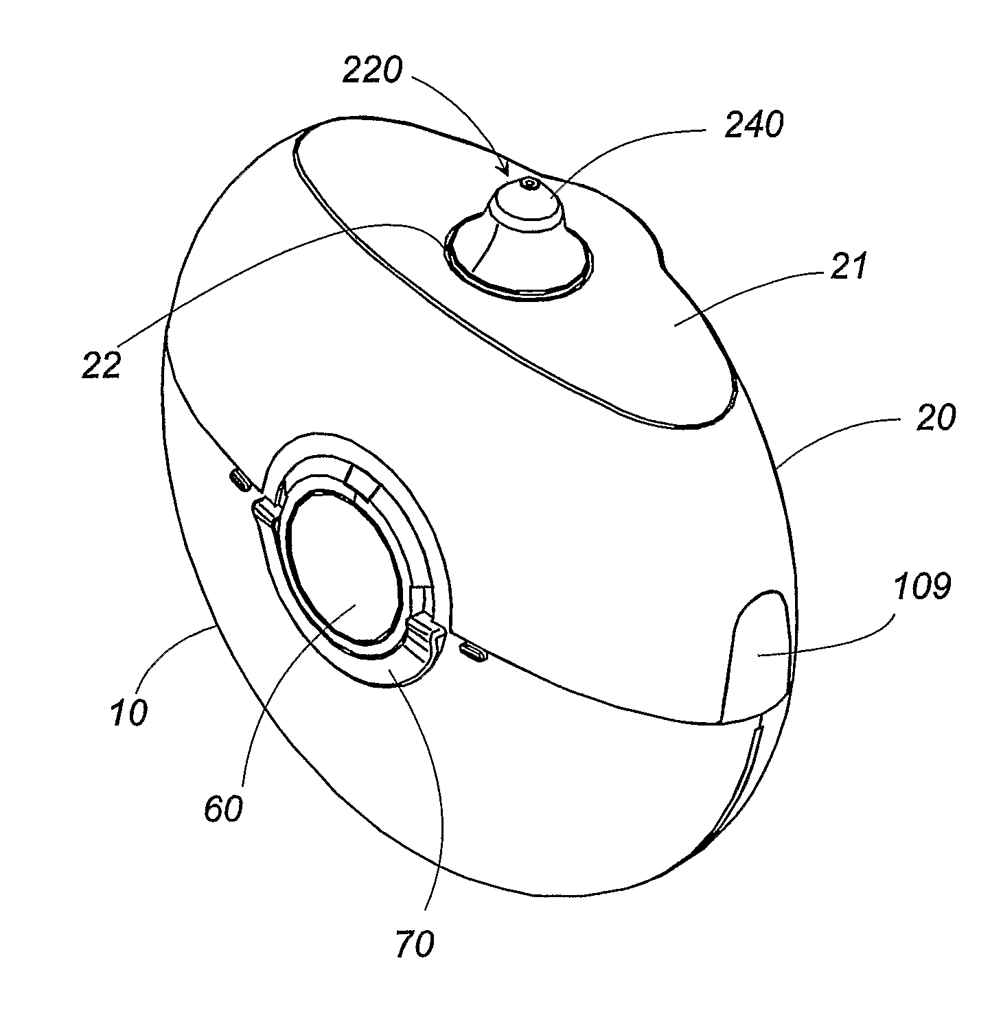
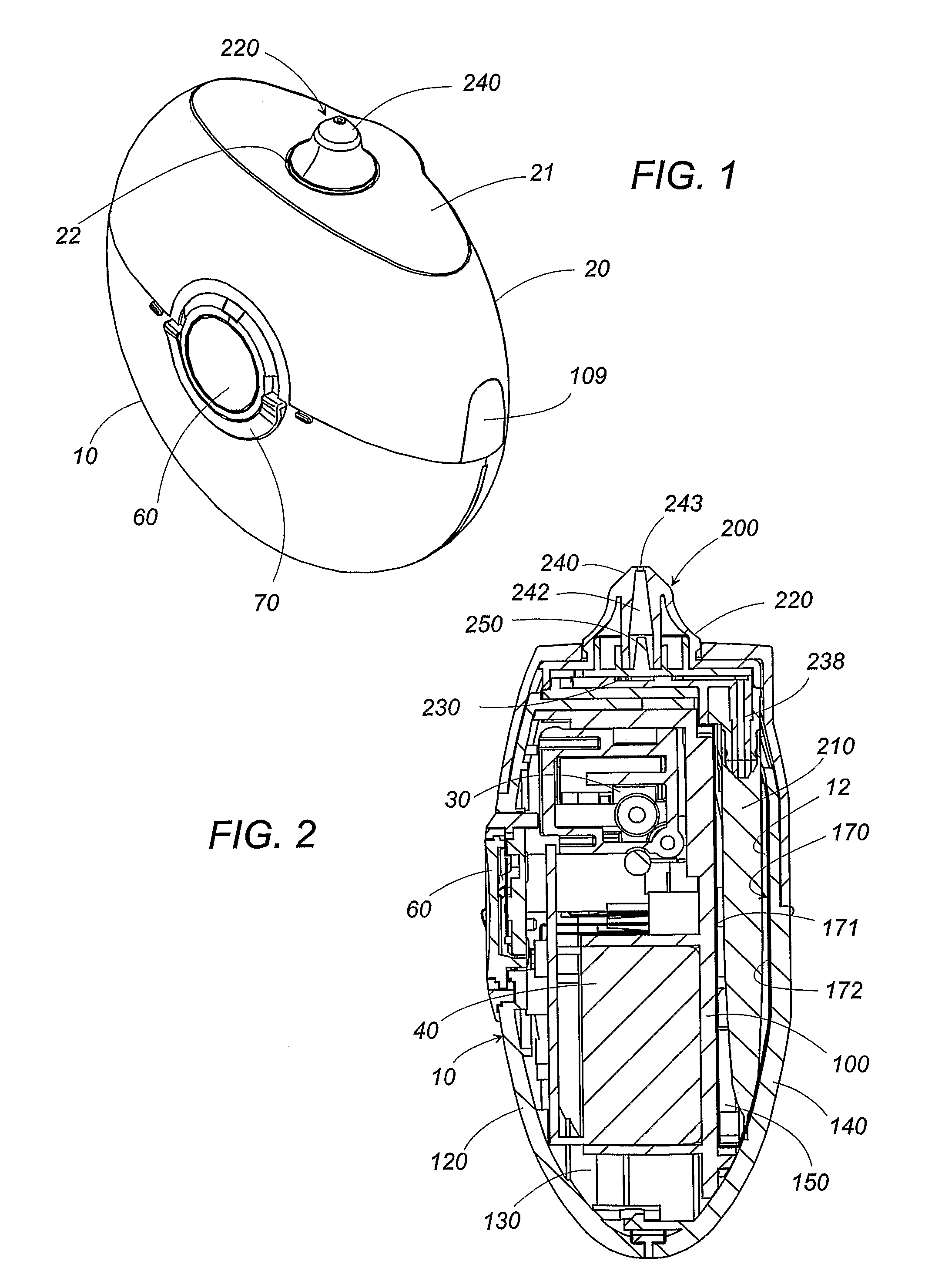
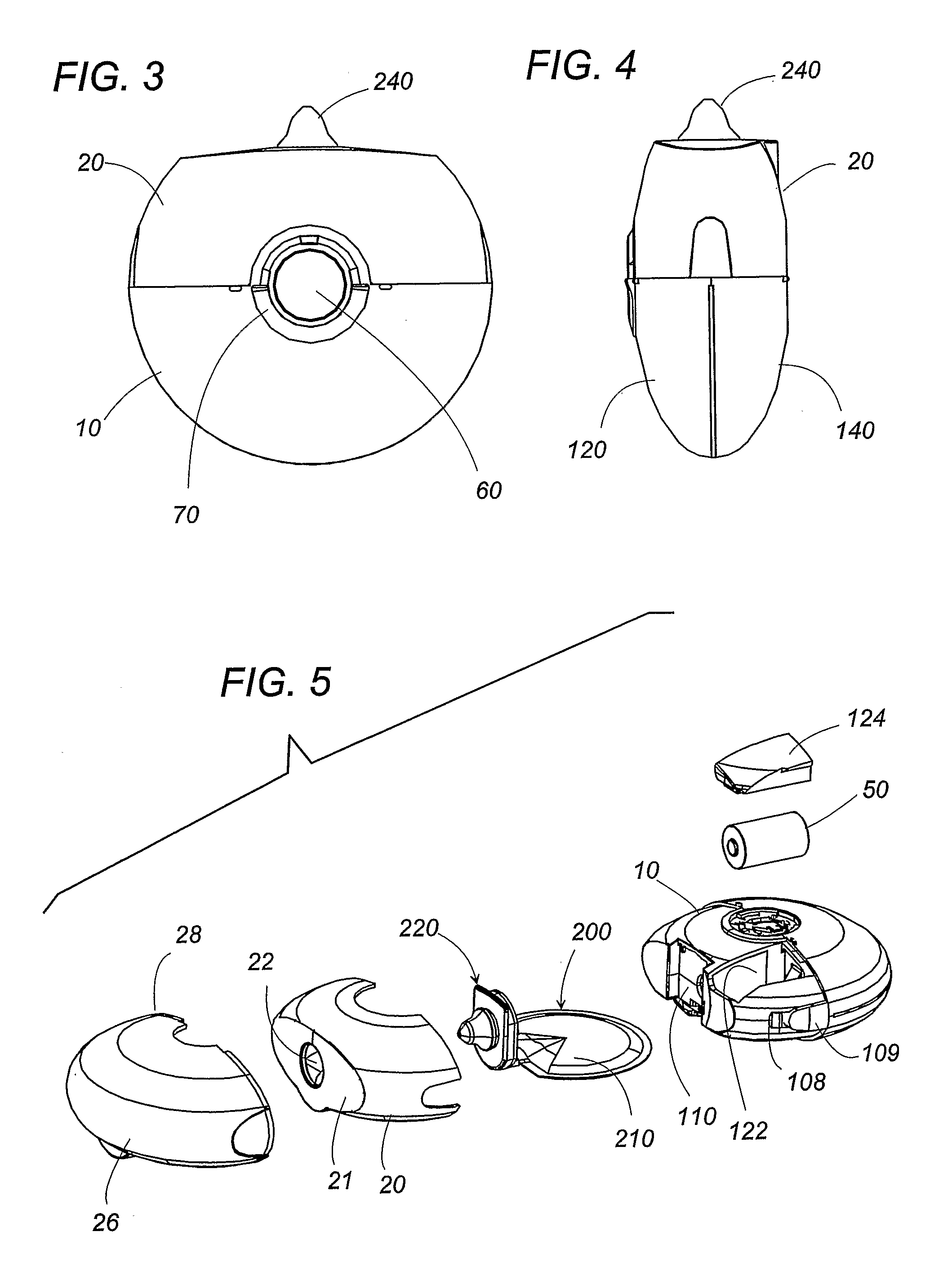
[0048]Now referring to FIGS. 1 to 7, there is shown an electrostatic spraying device in accordance with a preferred embodiment of the present invention. The device is configured into a self-contained portable structure that is compact enough to be easily carried with. The device is basically composed of a main body housing 10 and a removable cartridge 200 containing a volume of a liquid composition to be electrostatically sprayed according to a mechanism already disclosed in WO 01 / 12336, WO 01 / 12335, US 2001-0020653A, US 2001-0038047A, US 2001-0020652A, US 2001-0023902A, and WO 03 / 072263, incorporated herein by reference. The liquid composition utilized in the device include those disclosed in WO 03 / 072263, also incorporated herein by reference, i.e., an emulsion having conductive and insulating phases, although not limited thereto.

[0049]The housing 10 is dimensioned to be grasped by a user's hand and incorporates an electric motor 30, a high voltage generator 40, and a battery 50, ...


PUM


Abstract

An electrostatic spraying device has a capability of confirming that the device is ready for making an electrostatic spraying of the liquid composition on a user's skin. The device includes a nozzle and a pump for dispensing the liquid composition out through the nozzle. An emitter electrode is disposed to electrostatically charge the liquid composition being dispensed for making the electrostatic spraying. The device is provided with a power switch and a selector for selection between a spraying mode and a dripping mode. In the dripping mode, the pump is alone actuated to dispense the liquid composition absent electrostatic charge. In the spraying mode, both of the pump and the emitter electrode are activated to make the electrostatic spraying. Thus, the user can be easy to drip the liquid composition by simply manipulating the selector prior to initiating the electrostatic spraying.

Description

TECHNICAL FIELD[0001]The present invention relates to an electrostatic spraying device for personal use, and more particularly to a device for spraying a liquid composition by means of an electrostatic force.BACKGROUND OF THE INVENTION[0002]WO 03 / 072263 discloses an electrostatic spraying device having a removable cartridge containing a volume of a liquid composition. The device includes a plunger pump that displaces the liquid out of the reservoir and a nozzle for dispensing the liquid. The nozzle is provided with an emitter electrode which applies a high voltage to the liquid composition being supplied from the reservoir to the nozzle, i.e., electrostatically charge the particles of the liquid composition for spraying the composition on a user's skin by the electrostatic force. In order to start spraying the electrostatically charged liquid composition, the user is required to feed the liquid composition to the nozzle to drip it out of the nozzle and subsequently, after confirming...

Claims


Application Information

Patent Timeline
Patent Type & Authority Patents(United States)
IPC IPC(8): B05B5/00A62C11/00B05B7/26B05B7/00A61M11/00A61M15/00A62C13/62B65D35/28F04B35/04F04B17/00B65D35/00B67D7/60B05B5/025B05B5/053B05B5/16B05B9/08
CPCB05B5/005B05B5/0255B05B5/0533B05B5/1691B05B9/0861B05B9/0866
Inventor YAMAGUCHI, NAOKIASAKAWA, KOJIWILSON, DAVID EDWARDTOYAMA, KAZUMILIN, MEEI-LIH
Owner THE PROCTER & GAMBLE COMPANY
Learn More