
Process for automatic dynamic reloading of data flow processors (DFPs) and units with two- or three-dimensional programmable cell architectures (FPGAs, DPGAs, and the like)

a data flow processor and automatic dynamic reloading technology, applied in logic circuits, instruments, data conversion, etc., can solve the problems of inability to further process data, and inability to reconfigure the unit during operation, so as to achieve the effect of rapidly re-configuring the programmable unit and significantly more rapid re-configuration

Inactive Publication Date: 2010-10-26
SCIENTIA SOL MENTIS AG
View PDF657 Cites 13 Cited by
  • Summary
  • Abstract
  • Description
  • Claims
  • Application Information

AI Technical Summary

Benefits of technology

This solution enables rapid reconfiguration of programmable units, improving the utilization of existing elements and allowing multiple functions to be performed on the same data without stopping the unit's operation, thus overcoming static limitations and reducing configuration time.

Problems solved by technology

Most units (in particular FPGA units) cannot be reconfigured during operation.
For reconfigurable units, data usually cannot be further processed while the unit is being reconfigured, and the time required is very long.
This process is slow and usually requires hundreds of milliseconds due to the limited band width accessing the external memory where the configuration data is stored, after which the programmable unit is available for the desired / programmed function as described in the configuration file.
The existing methods and options present a series of problems, such as:If a configuration in a DFP (see German Patent Application No.
Therefore it takes a very long time to configure a large unit and often makes it impossible to do it during operation or affects the function of the unit.When a unit is partially configured during operation, a central logic entity is always used, through which all reconfigurations are managed.
This requires considerable communication and synchronization resources.

Method used


Image

  • Process for automatic dynamic reloading of data flow processors (DFPs) and units with two- or three-dimensional programmable cell architectures (FPGAs, DPGAs, and the like)
  • Process for automatic dynamic reloading of data flow processors (DFPs) and units with two- or three-dimensional programmable cell architectures (FPGAs, DPGAs, and the like)
  • Process for automatic dynamic reloading of data flow processors (DFPs) and units with two- or three-dimensional programmable cell architectures (FPGAs, DPGAs, and the like)

Examples


Embodiment Construction

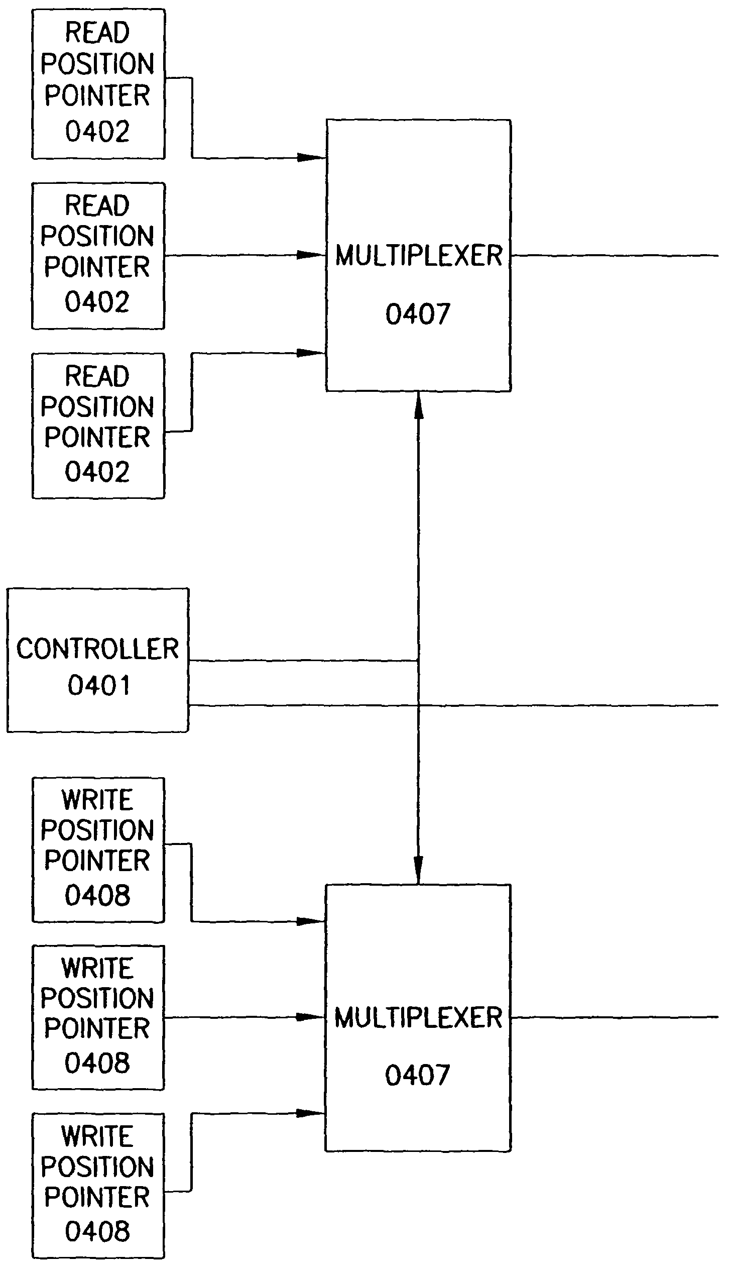
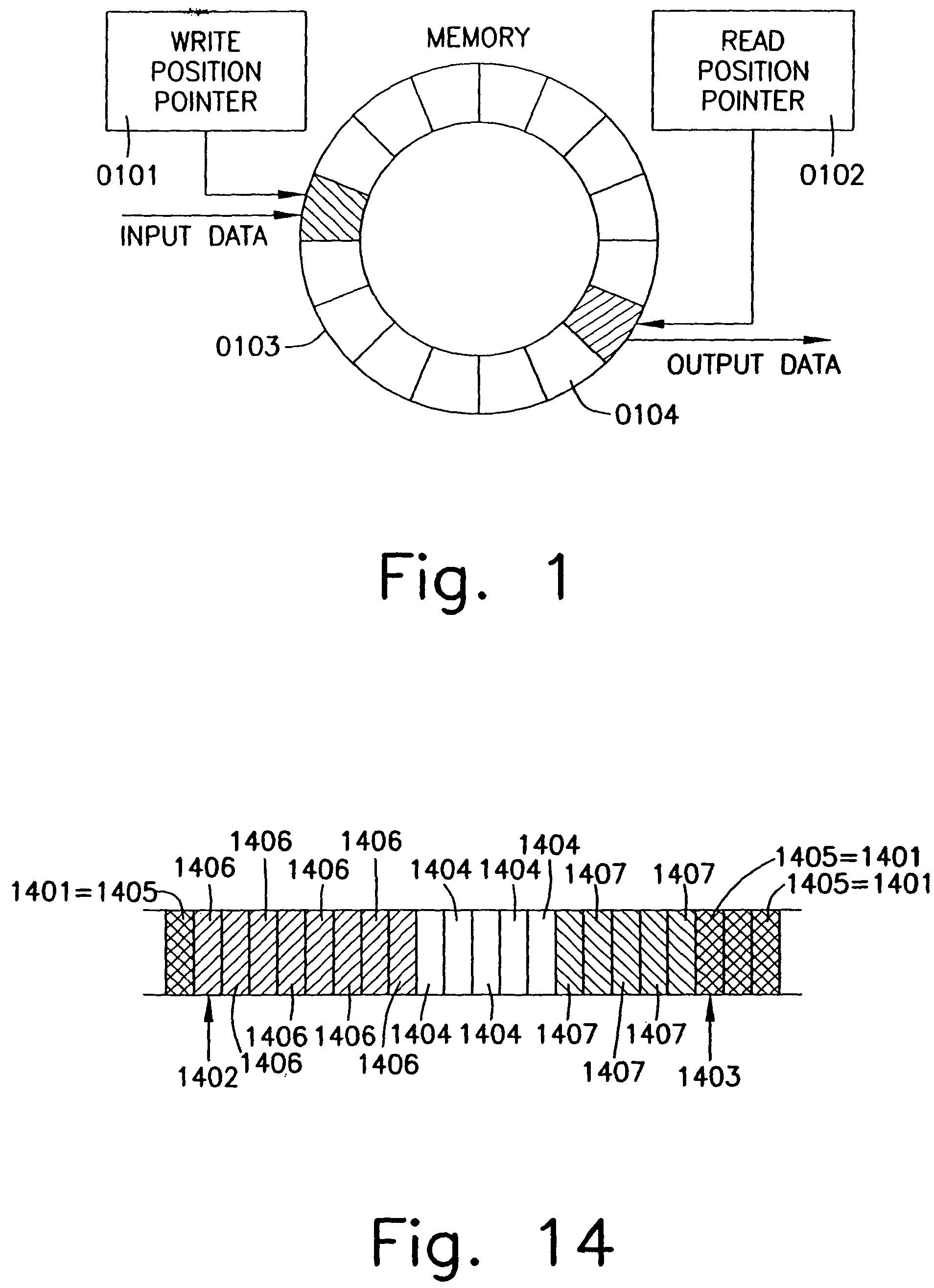
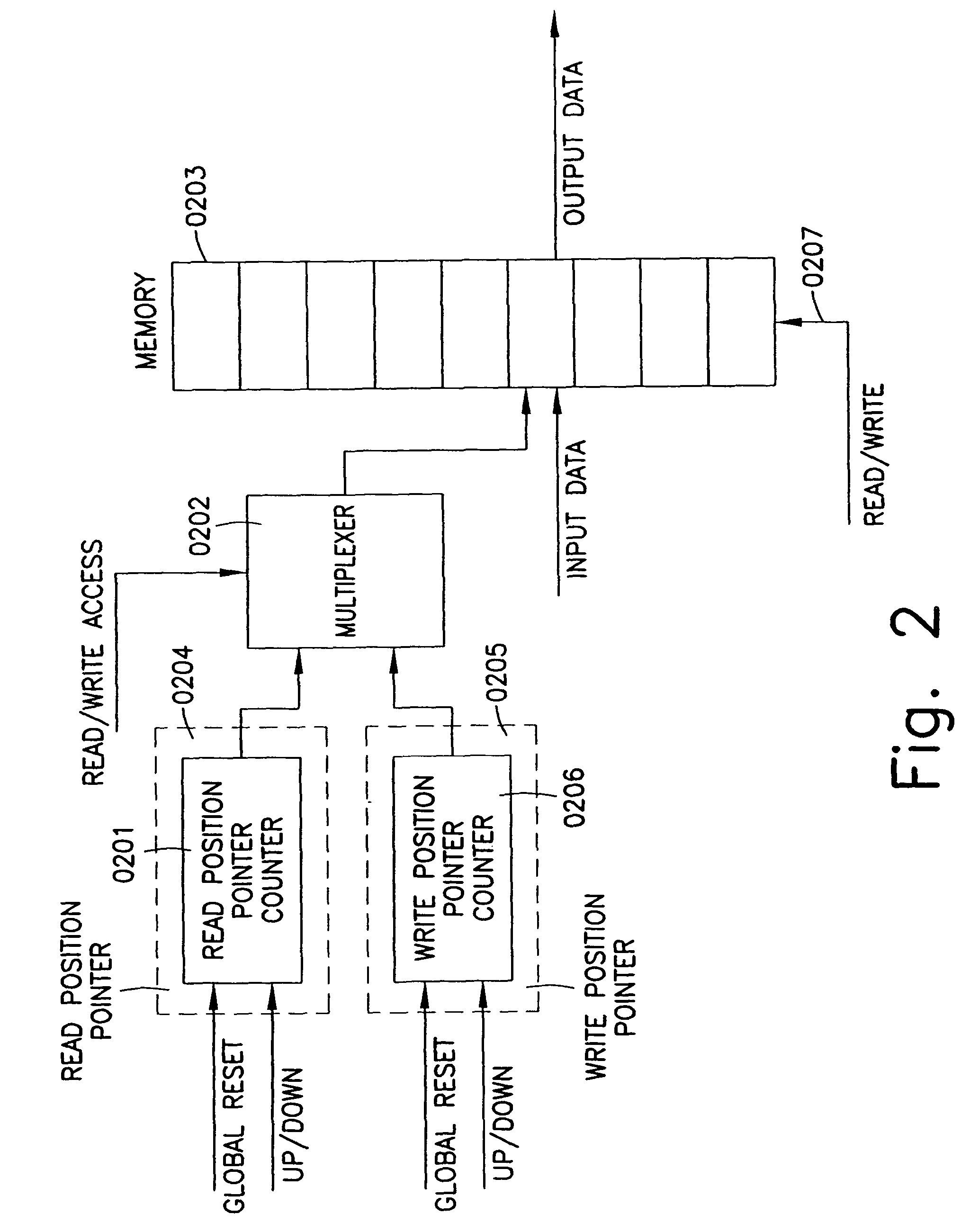
[0038]There is a plurality of ring memories in a programmable unit or connected externally to said unit. The one or more ring memories have one or more controllers controlling the one or more ring memories. These controllers are part of the PLU named in German Patent Application No. DE 44 16 881 A1. The ring memories contain configuration strings for the configurable elements of one or a plurality of configurable units; the configurable elements can also be expressly used for interconnecting function groups and they can be crossbar circuits or multiplexers for interconnecting bus architectures, which are conventional.

[0039]Ring memories and ring memory controllers can be either directly hardware-implemented or first obtained by configuring one or more configurable cells of a configurable unit (e.g., FPGA).

[0040]Conventional ring memories can be used as ring memories, in particular ring memories and / or controllers with the following properties:[0041]where not all records are used, an...


PUM


Abstract

In a data-processing method, first result data may be obtained using a plurality of configurable coarse-granular elements, the first result data may be written into a memory that includes spatially separate first and second memory areas and that is connected via a bus to the plurality of configurable coarse-granular elements, the first result data may be subsequently read out from the memory, and the first result data may be subsequently processed using the plurality of configurable coarse-granular elements. In a first configuration, the first memory area may be configured as a write memory, and the second memory area may be configured as a read memory. Subsequent to writing to and reading from the memory in accordance with the first configuration, the first memory area may be configured as a read memory, and the second memory area may be configured as a write memory.

Description

CROSS-REFERENCE TO RELATED APPLICATIONS[0001]This application is a continuation of U.S. patent application Ser. No. 10 / 265,846, filed Oct. 7, 2002, now U.S. Pat. No. 7,028,107 which is a continuation of U.S. patent application Ser. No. 09 / 613,217, filed Jul. 10, 2000, now U.S. Pat. No. 6,477,643, which is a continuation of U.S. patent application Ser. No. 08 / 947,002 filed on Oct. 8, 1997, now U.S. Pat. No. 6,088,795, expressly incorporated herein by reference in the entirety.FIELD OF THE INVENTION[0002]The present invention is directed to a process for automatic dynamic reloading of data flow processors.BACKGROUND INFORMATION[0003]Programmable units presently used (DFPs, FPGAs—Field Programmable Gate Arrays) can be programmed in two different ways:[0004]one-time only, i.e., the configuration can no longer be changed after programming. All configured elements of the unit perform the same function over the entire period during which the application takes place.[0005]on site, i.e., the...

Claims


Application Information

Patent Timeline
Patent Type & Authority Patents(United States)
IPC IPC(8): G06F3/00G06F15/76G06F15/82G06F15/78G06F17/50H03K19/177
CPCG06F15/7867H03K19/17752H03K19/17756H03K19/1776H03K19/17776H03K19/17758
Inventor VORBACH, MARTINMUNCH, ROBERT
Owner SCIENTIA SOL MENTIS AG
Learn More