
Device and method for counting elementary particles emitted by a fluid in a conduit

Inactive Publication Date: 2010-10-26
COMMISSARIAT A LENERGIE ATOMIQUE ET AUX ENERGIES ALTERNATIVES
View PDF15 Cites 0 Cited by
  • Summary
  • Abstract
  • Description
  • Claims
  • Application Information

AI Technical Summary

Benefits of technology

[0008]The object of the present invention is to propose a device for counting elementary particles emitted by a fluid, the device comprising a line for transferring this fluid and, placed outside said line, detection means for detecting these particles, said particles being attenuated by a wall of said line and / or by this fluid, which device remedies the aforementioned drawbacks by having an improved measurement sensitivity.
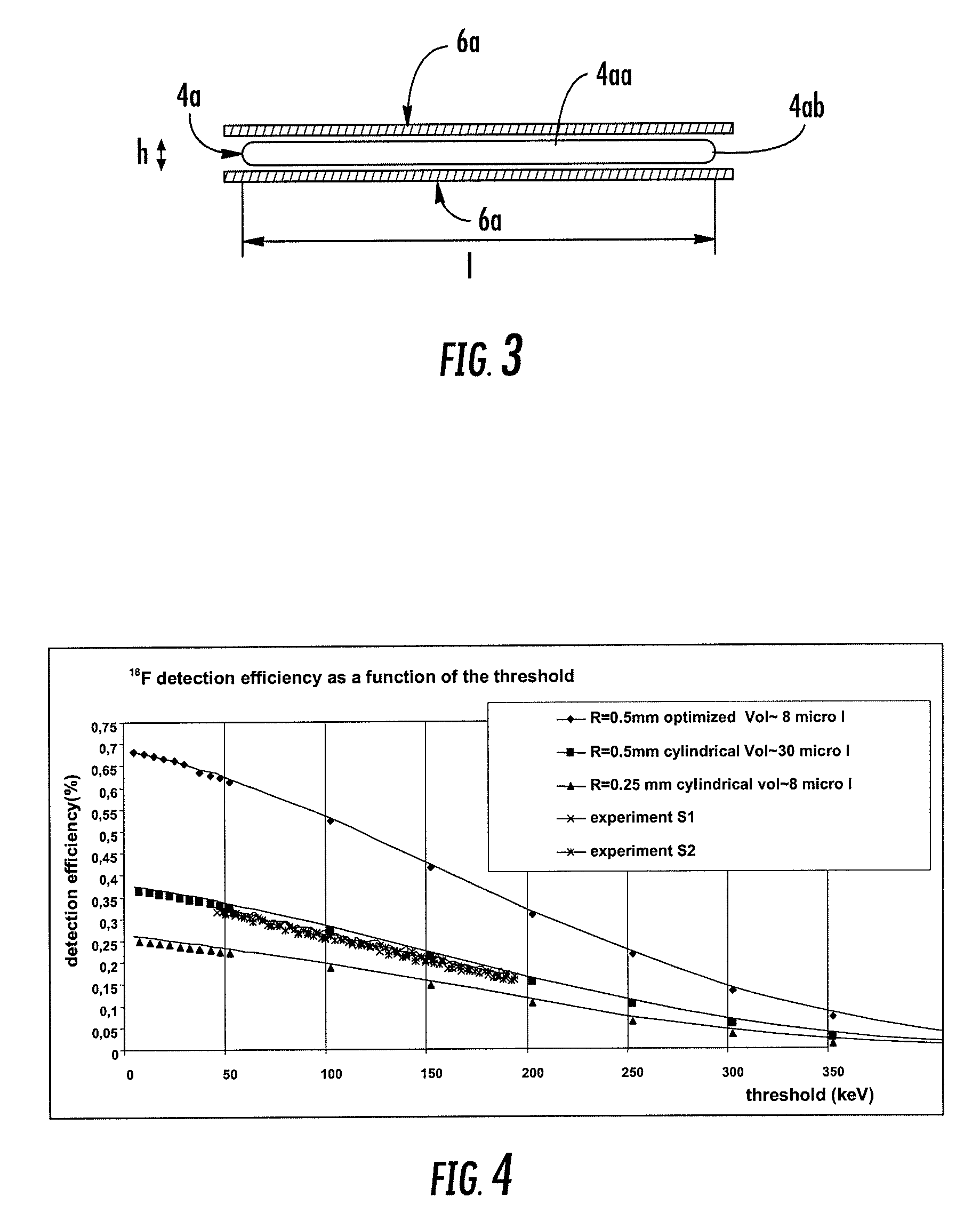
[0010]It will be noted that if the particles to be counted are electrons or positrons, this extremely flattened geometry of the counting portion combined with its relatively high internal width, said detection means being arranged so as to face said width and overhang it, gives a very high counting efficiency, typically greater than 50% both for 18F and 11C radiotracers, thus making measurements possible even on blood microsamples having a volume of less than 10 μl (typically those taken from mice) and possibly containing short-lived radiotracers (such as 11C).
[0011]In particular, it should be noted that this arrangement of said detection means, both facing and overhanging the transverse width of the counting portion makes it possible to maximize the geometric acceptance of these detection means (i.e. to maximize all the directions in space in which a radiotracer molecule may emit an elementary particle whose path impacts the detection means, making its “capture” possible), thus contributing to proving this counting efficiency.
[0022]It will be noted that this selection of such a “Kapton”-type polyimide makes it possible to obtain this very low value of the aforementioned product e×d, compared with the usual values of this product, which are generally between 150 and 200 in the case of the known lines made of LDPE, which have a lower density than that of this “Kaptonpolyimide but have a very substantially greater thickness.
[0023]According to another feature of the invention, said detection means advantageously comprise two sets of detectors placed respectively against or in the immediate vicinity of two approximately plane large faces of said counting portion, which faces are separated from each other by said height and are joined together by two small faces of this portion, these sets of detectors overhanging said small faces in the direction of said width in order to maximize the geometric acceptance of said detectors.
[0028]According to a second exemplary embodiment of the invention, the particles are electrons or positrons emitted by beta-radioactivity, said wall having a thickness e, expressed in μm, and a density d, expressed in g / cm3, such that the product e×d is less than 100 and preferably less than 50, so as to minimize the absorption of these particles so as not to significantly affect the counting.

Problems solved by technology

As is known, the counting of particles attenuated by certain components of a fluid that incorporates them and / or by the wall of the line transferring this fluid poses certain technical problems, which are particularly acute in the particular case of counting within small fluid samples, in the case of absorption of these particles by the fluid, or else in the case when the particles to be counted are electrons or positrons emitted by beta-radioactivity in particular.
One major drawback of this lineless solution is that the radiotracer accumulated in the other organs of the animal creates a strong perturbation by gamma-radiation.
Another drawback of this solution lies in the small dimensions characterizing the measurement, which leads to a low counting efficiency.

Method used


Image

  • Device and method for counting elementary particles emitted by a fluid in a conduit
  • Device and method for counting elementary particles emitted by a fluid in a conduit
  • Device and method for counting elementary particles emitted by a fluid in a conduit

Examples


Embodiment Construction

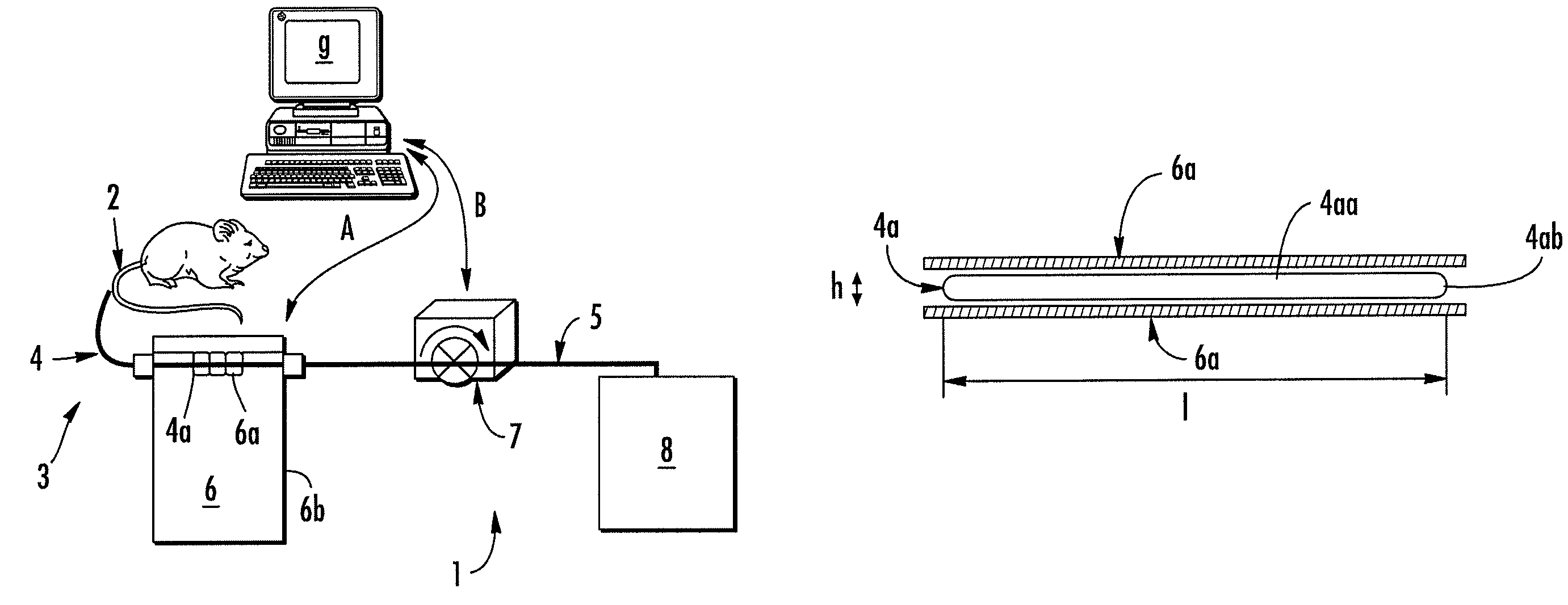
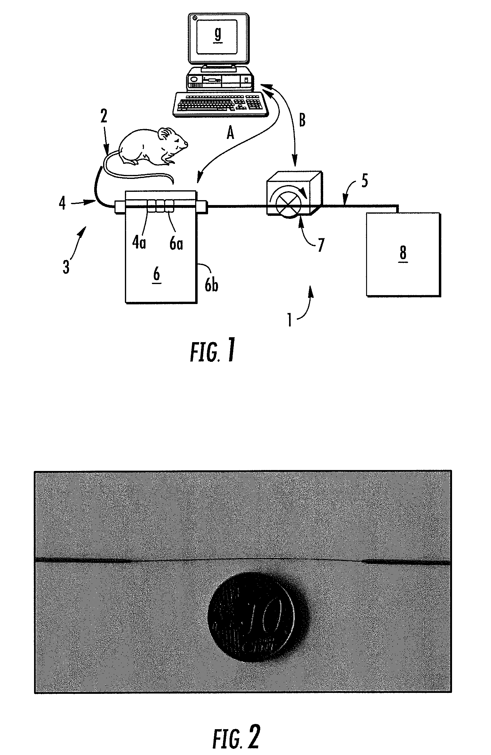
[0037]FIG. 1 illustrates by way of example an automated installation 1 for carrying out, in succession and continuously, the taking of blood microsamples from a small mammal 2, for example of the rat or mouse type, for temporarily storing said microsamples and for carrying out radioactive measurements thereon, by means of a sampling system 3 that includes a succession of lines 4 and 5 of the flexible capillary or microtube type. This sampling system 3 essentially comprises:[0038]a catheter which is equipped with a connection device (not illustrated) and is intended for sucking up, in bursts, the same amount of blood to be taken, via a peristaltic pump 7;[0039]a counting device 6 for counting the particles present in the microsamples taken, which in this example is a counter 6 that counts positrons or electrons resulting from the beta-radioactivity for total blood microsamples and which is placed as close as possible to the sampling point, being virtually in contact with a counting p...


PUM


Abstract

The invention relates to a device and a method for counting elementary particles emitted by a fluid, the device comprising a line for transferring the fluid and, outside the line, detection means (6a) for detecting the particles that are attenuated by a wall of the line and / or by this fluid.A counting device according to the invention includes at least one counting portion (4a) of oblong cross section which joins together two adjacent portions of the line having a larger flow section and which has an [internal height (h) / internal width (l)] ratio of 20% or less, in which the internal height and the internal width represent the smallest and largest transverse dimensions respectively of the portion, these being measured along two approximately perpendicular directions, said detection means extending transversely to this portion, facing its entire internal width and on either side thereof.

Description

FIELD AND BACKGROUND OF THE INVENTION[0001]The present invention relates to a device and a method for counting elementary particles (such as α-particles, γ-particles, electrons or positrons) emitted by a fluid, the device having a line for transferring this fluid and, outside the line, means for detecting these particles that are attenuated by a wall of the line and / or by this fluid. The invention applies more particularly, but not exclusively, to a fluid consisting of blood microsamples taken from a mammal.[0002]As is known, the counting of particles attenuated by certain components of a fluid that incorporates them and / or by the wall of the line transferring this fluid poses certain technical problems, which are particularly acute in the particular case of counting within small fluid samples, in the case of absorption of these particles by the fluid, or else in the case when the particles to be counted are electrons or positrons emitted by beta-radioactivity in particular. Among t...

Claims


Application Information

Patent Timeline
IPC IPC(8): G01N15/00G01N33/48
CPCA61B5/1427A61B6/4258A61B6/508A61B6/481A61B2503/40A61B5/150022A61B5/150229A61B5/15087A61B5/155
Inventor REYMOND, JEAN-MARCKERHOAS-CAVATA, SOPHIEMANGEOT, PHILIPPE
Owner COMMISSARIAT A LENERGIE ATOMIQUE ET AUX ENERGIES ALTERNATIVES
Learn More