
Sensing sensor

Active Publication Date: 2017-10-05
NIHON DEMPA KOGYO CO LTD
View PDF0 Cites 0 Cited by
  • Summary
  • Abstract
  • Description
  • Claims
  • Application Information

AI Technical Summary

Benefits of technology

The disclosure is about a sensor that improves the measurement of a certain substance by using less space. The technical effect of this invention is that it increases the sensitivity of the sensor by reducing the space needed for the sample solution.

Problems solved by technology

However, shape variations of a fitted cover may collapse the channel or break the crystal resonator when a channel forming member is pressed.

Method used


Image

  • Sensing sensor
  • Sensing sensor
  • Sensing sensor

Examples


Embodiment Construction

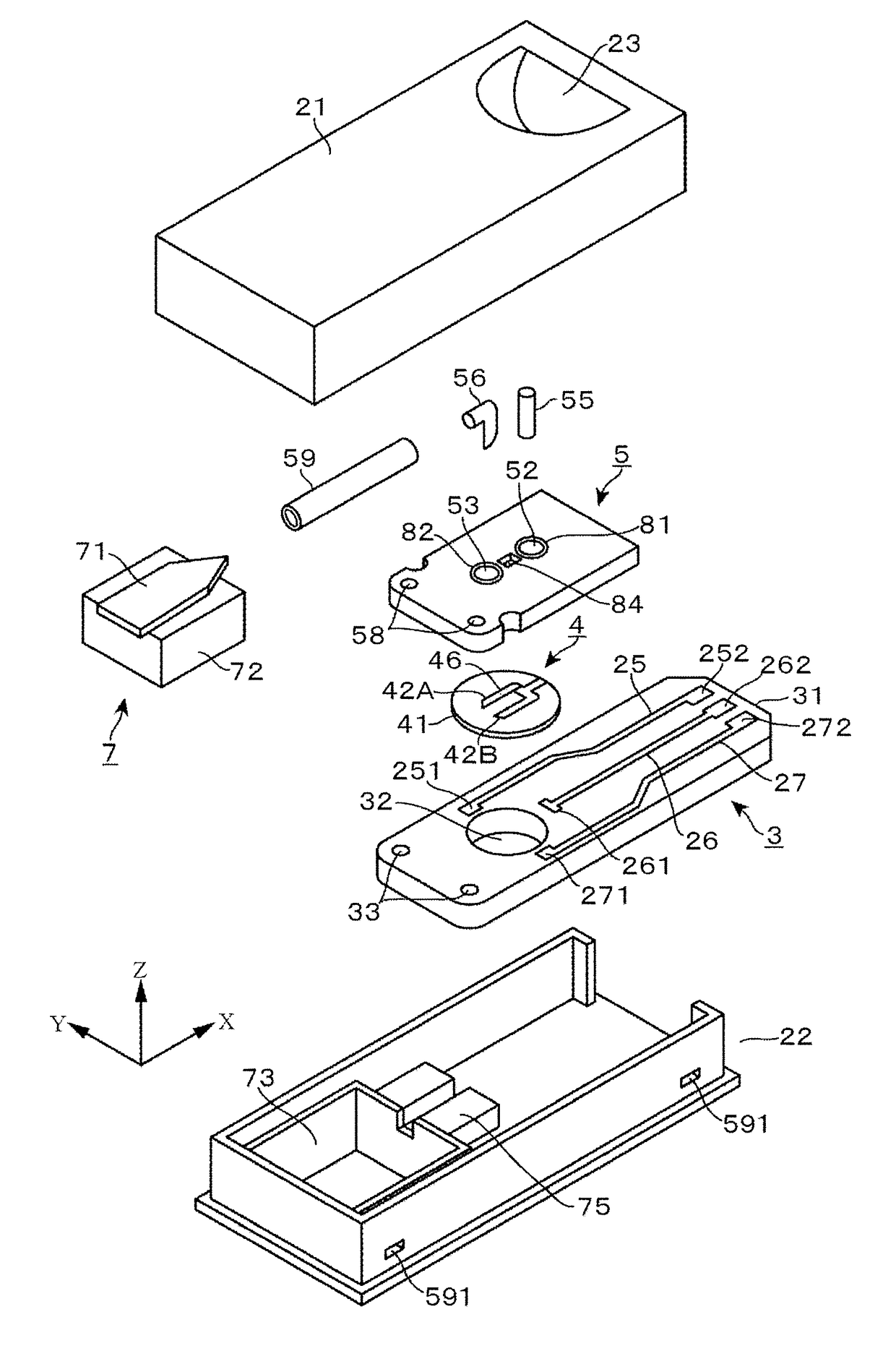
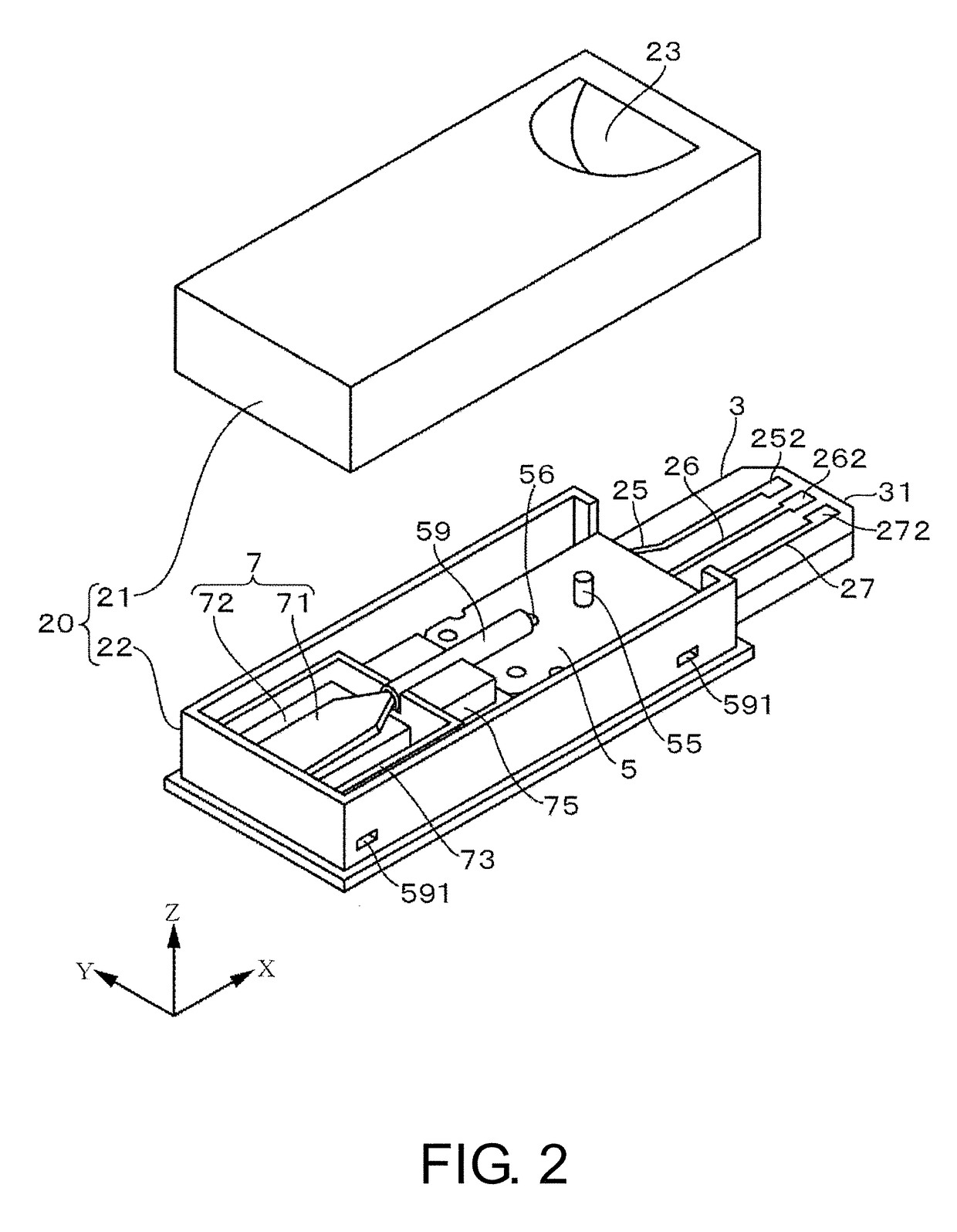
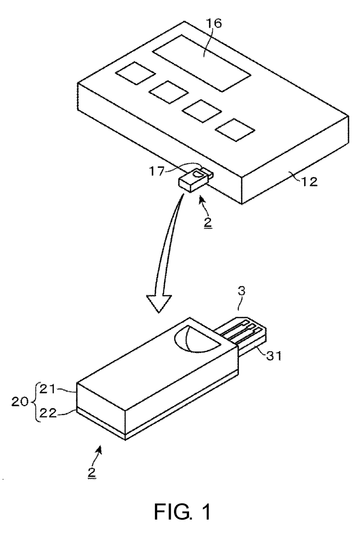
[0024]The following describes a sensing device using a sensing sensor according to an embodiment of the disclosure. This sensing device uses a microfluidic chip. The sensing device is configured to detect, for example, presence / absence of an antigen, such as virus, in a sample solution obtained from nasal cavity swab of a human so as to determine whether the human has been infected with virus or not with the microfluidic chip. As illustrated in an external perspective view in FIG. 1, the sensing device includes a main body 12 and a sensing sensor 2. The sensing sensor 2 is attachably / detachably connected to an insertion port 17 that is formed in the main body 12. The main body 12 includes, for example, a display 16 constituted by a liquid crystal display screen on a top surface. The display 16 displays, for example, an output frequency of an oscillator circuit, which is disposed in the main body 12 and will be described later, a measurement result, such as an amount of frequency tra...


PUM


Abstract

One side of the surfaces of the crystal resonator 4 including an adsorbing film 46 that absorbs a sensing object on an excitation electrode 42A is pressed with the channel forming member 5 using the upper-side cover body 21 to fonn a channel 57, which runs from one end side to the other end side on one side of surfaces of the crystal resonator 4. A depressed portion 84 is disposed in at least one of: a position opposed to the channel 57 and at a surface on an opposite side of the channel 57 in the channel forming member 5, and a position opposed to the channel 57 and at a surface on the opposite side of the channel 57 in the pressing member with respect to the channel forming member 5.

Description

TECHNICAL FIELD[0001]The disclosure relates to a sensing sensor for sensing a sensing object contained in a sample solution based on oscillation frequency of piezoelectric resonator.BACKGROUND ART[0002]In a clinical field, a simple method called Point of Core TEST (POCT), which is typified by a self-monitoring of blood glucose level, for example, is spreading. As an example of this method, Patent Document 1 describes a sensing sensor using Quartz Crystal Microbalance (QCM) and discloses a structure that forms a housing space for a sample solution between an upper-side case and a crystal resonator by placing the crystal resonator on a wiring board and engaging the upper-side case and a lower-side case with each other. As a sensitivity enhancing technique of QCM, there are twin sensors that perform a differential measurement. This technique forms two electrodes symmetrically with respect to a channel on one crystal such that the sample solution simultaneously and similarly flows with ...

Claims


Application Information

Patent Timeline
IPC IPC(8): G01N33/487G01N29/036
CPCG01N33/48785G01N29/2437G01N29/036G01N9/002G01N29/022G01N29/2443G01N2291/0256
Inventor KUKITA, HIROYUKI
Owner NIHON DEMPA KOGYO CO LTD
Learn More