
Electromotive linear drive

a linear drive and electric motor technology, applied in the direction of generator/motor, instruments, gears, etc., can solve the problems of relatively high assembly cost, and adverse effects on assembly ease, so as to achieve the effect of further reducing the number of components

Active Publication Date: 2010-10-26
DEWERTOKIN TECHNOLOGY GROUP CO LTD
View PDF23 Cites 8 Cited by
  • Summary
  • Abstract
  • Description
  • Claims
  • Application Information

AI Technical Summary

Benefits of technology

[0007]The invention is based on the object to configure an electromotive drive of a type as described above in greater detail, which can be made more cost-efficiently compared to conventional designs and is more assembly-friendly.
[0010]As the connections in radial directions are implemented by rotary motions, the connection zones can be manufactured especially easily because the rotary motions can be realized by structurally simple means.
[0016]Although the interlocking threads can be firmly tightened, so that a certain force application for reversal is required, it is provided to additional secure the connections. This may be realized, for example, by using resilient tongues, bolts, or pins, which engage in respective recesses. In this way, a certain position especially for the attachment part would be secured.
[0017]Resilient locking elements have the further advantage that no additional securing elements, for example bolts or the like, have to be rotated into the housing or motor pot or the attachment element.
[0036]The spindle is suitably connected form-fittingly on the motor-proximal side with the wheel by which it is propelled, for example tumbled, pinned, toothed, or the connection is realized by upsetting. The need for additional connecting elements may thus be eliminated.
[0040]As the linear drives involved here are mass articles which should be manufactured in an inexpensive manner, the number of components can be further decreased by widening or thickening the housing-distal spindle end for implementing a form-fitting end stop for the spindle nut.

Problems solved by technology

Although the use of one mold is thus only required to make this form part through an injection molding process, the ease of assembly is, however, adversely affected thereby.
As such drives are manufactured on a large scale, assembly costs are relatively high.

Method used


Image

  • Electromotive linear drive
  • Electromotive linear drive
  • Electromotive linear drive

Examples


Embodiment Construction

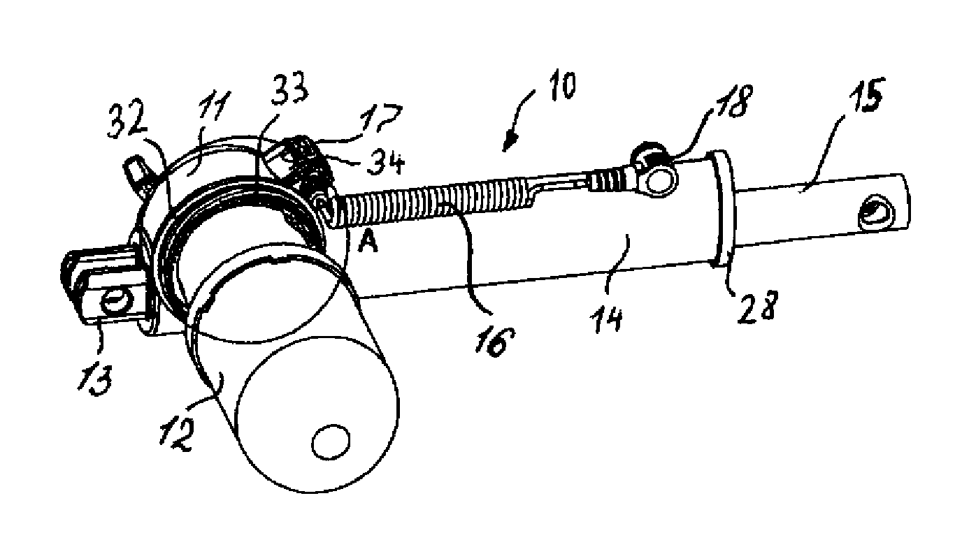
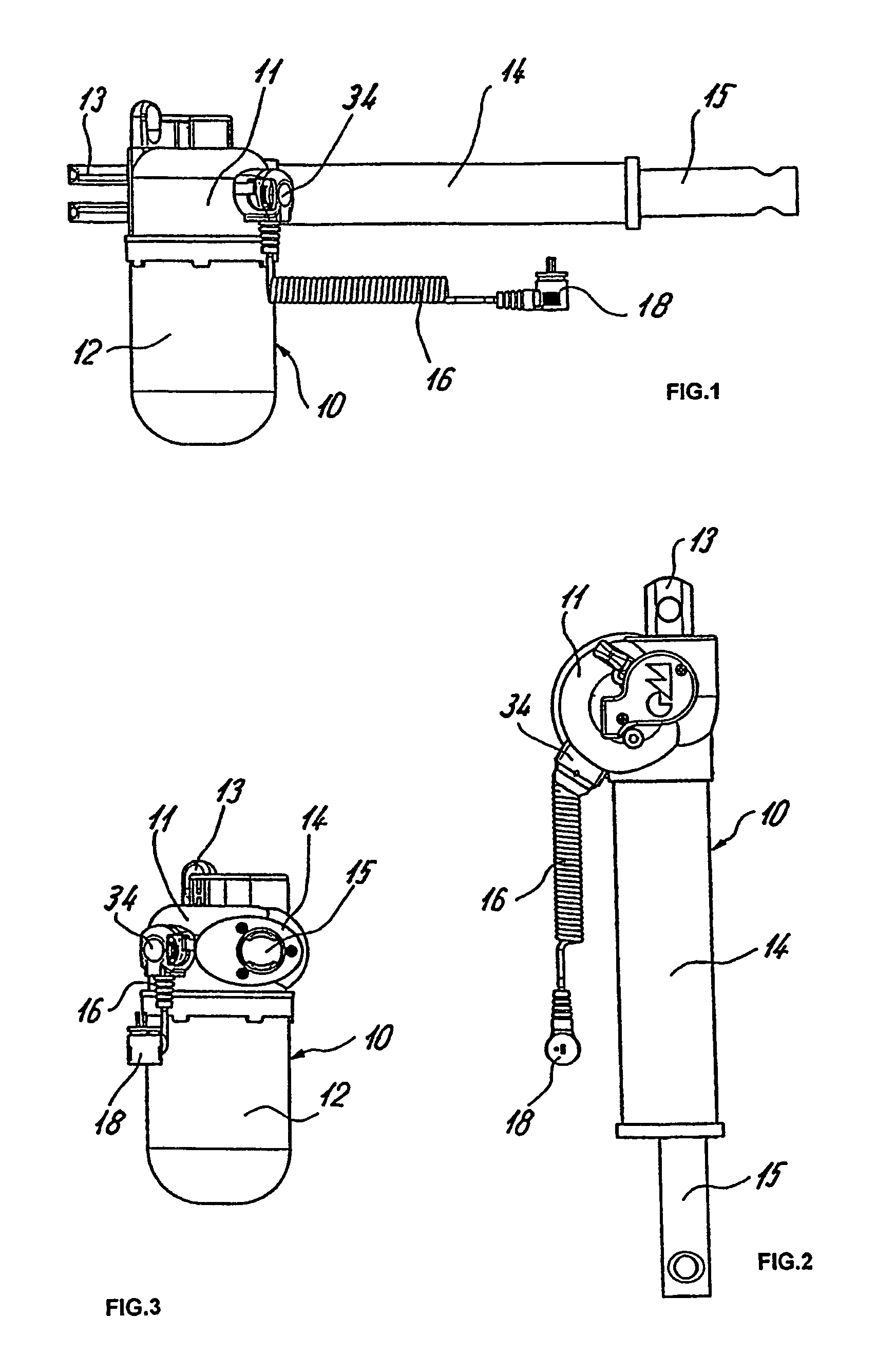
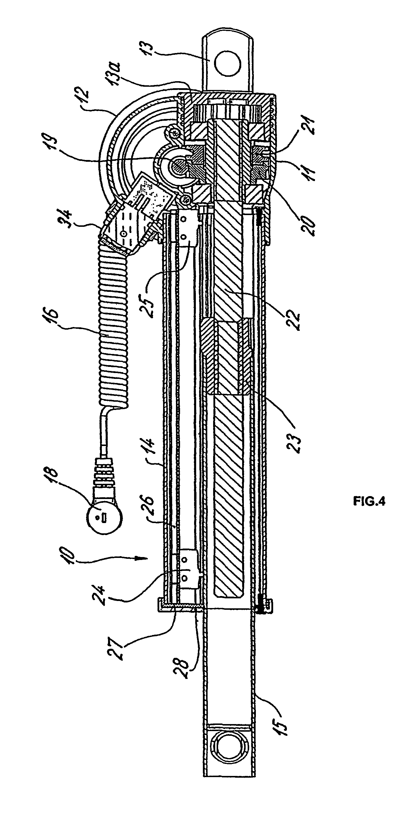
[0050]The linear drive 10 illustrated in the Figures has a housing 11 which has attached thereto a motor pot 12 in a manner yet to be described in more detail, an attachment element in the form of a fork head 13, and a flanged tube 14.

[0051]The linear drive is further provided with an extendible lifting tube 15 which is guided in the flanged tube 14 in a manner yet to be described in more detail.

[0052]The afore-described components may be made of plastic.

[0053]The power supply of the linear drive 10 is realized via a power feed cable 16 which is provided on both ends with plugs 17, 18. The plug 17 may be inserted in a socket receptacle which is mounted in or on the housing 11. In a manner not shown in detail, each individual conductor of the power feed cable 16 has its own plug or has a continuing connection element with the continuing conductor. The plug 18 is inserted in a socket receptacle of a transformer with downstream converter.

[0054]FIG. 4 shows the basic configuration of th...


PUM


Abstract

An electromotive linear drive unit comprising a housing, a motor pot, a connection piece, a power supply cable, a deployable lifting tube, and a fixed flanged tube is designed in such a way that it can be made at a low cost while being easier to assemble than previously known embodiments thereof. In accordance with the invention, at least the connection zones of the housing (11) to the motor pot (12) and the attachment part (13) are configured in a cylindrical manner while the connection zone are formed by means of a rotary motion of the housing (11) and / or the motor pot (12) and / or the attachment part (13) in a radial direction. The connection zones are configured form-fittingly in an axial direction. This type of connection is realized by means of meshing threads. The linear drive according to the invention is particularly suitable for driving the adjustable components of a slatted frame or armchair.

Description

BACKGROUND OF THE INVENTION[0001]The invention relates to an electromotive linear drive having a housing, a motor pot, an attachment element as well as a power feed cable, an extendible lifting tube, and a fixed flanged tube.[0002]The electromotive drive involved here is applicable in particular for adjusting moving parts of a piece of furniture, for example a slatted frame, an armchair, and the like. A preferred embodiment of the linear drive involves a spindle drive, i.e. a spindle is rotatably driven via a gear mechanism to reduce the motor speed. A spindle nut restrained against rotation travels upon the spindle.[0003]The spindle nut is connected to the lifting tube which is linked in driving relationship with the component to be adjusted. This may be implemented via a simple lever or via a fitting, for example.[0004]The lifting tube may be configured either as attachment element in its free end zone or an attachment element, for example a fork head, may be placed thereon.[0005]...

Claims


Application Information

Patent Timeline
Patent Type & Authority Patents(United States)
IPC IPC(8): F16H27/02F16H25/20H02K5/00H02K5/15H02K5/22H02K7/06
CPCF16H25/20H02K5/15H02K5/225H02K7/06F16H25/2015F16H2025/2084Y10T74/18656F16H2025/209
Inventor HANEBALL, FRANKMULLER, CHRISTIAN
Owner DEWERTOKIN TECHNOLOGY GROUP CO LTD
Learn More