
Digital broadcasting receiving apparatus with channel estimation function

a digital broadcasting and channel estimation technology, applied in the field of digital broadcasting receiving apparatuses with channel estimation functions, can solve the problems of radio interference, degrading the estimation accuracy of transmission lines, and both technologies cannot cope with an environment, so as to improve the channel estimation level and improve the receiving performance of digital broadcasting receiving apparatuses

Inactive Publication Date: 2010-10-19
MITSUBISHI ELECTRIC CORP
View PDF10 Cites 13 Cited by
  • Summary
  • Abstract
  • Description
  • Claims
  • Application Information

AI Technical Summary

Benefits of technology

The present invention provides a digital broadcasting receiving apparatus with a channel estimation function that can improve channel estimation even during the traveling of a mobile vehicle. The apparatus includes a Fourier transform circuit, a mode output section, and a channel estimation section. The channel estimation section generates a delay profile signal and a decision signal about the presence or absence of ghosts, which can occur during the traveling of a mobile vehicle. The delay profile signal and the decision signal are stored or outputted as channel estimation information. This allows the apparatus to improve its receiving performance and recognize not only the normal delayed wave, but also the presence or absence of ghosts.

Problems solved by technology

Both the technologies, however, cannot cope with an environment in which the digital broadcasting receiving apparatus is mounted on a mobile vehicle traveling at a high speed.
Thus, even if it produces the delay profile under the high-speed transfer environment, the conventional example 1 with the foregoing configuration cannot detect the presence of the ghosts, which presents a problem of degrading the estimation accuracy of the conditions of the transmission line.
As a result, it provides a problem of bringing about a malfunction, thereby causing radio interference.

Method used


Image

  • Digital broadcasting receiving apparatus with channel estimation function
  • Digital broadcasting receiving apparatus with channel estimation function
  • Digital broadcasting receiving apparatus with channel estimation function

Examples


embodiment 1

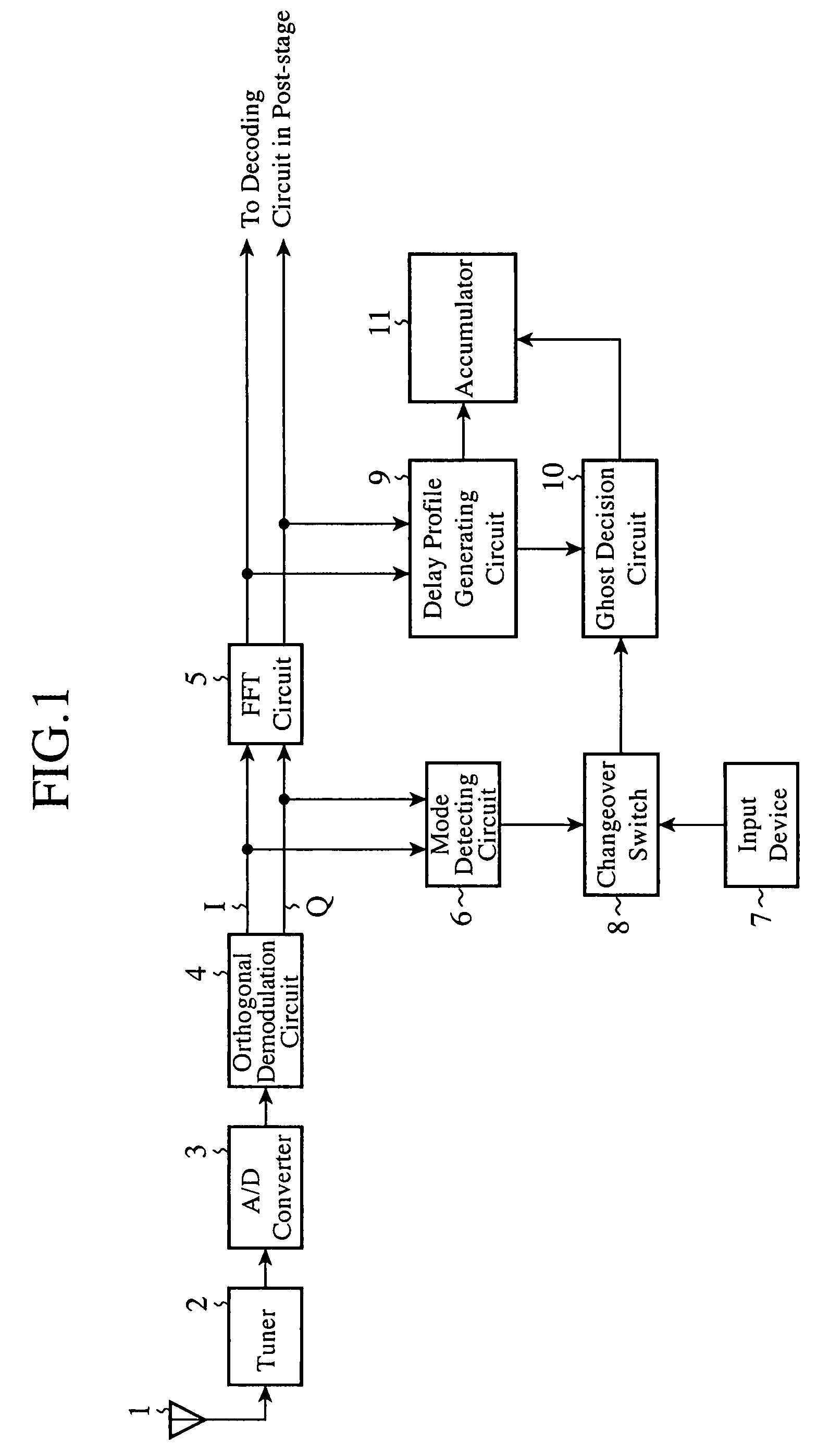
[0026]FIG. 1 is a block diagram showing a configuration of a digital broadcasting receiving apparatus with a channel estimation function of an embodiment 1 in accordance with the present invention.

[0027]In FIG. 1, the digital broadcasting receiving apparatus with a channel estimation function comprises a receiving antenna 1, a tuner 2, an A / D converter 3, an orthogonal demodulation circuit 4, a Fourier transform circuit (called “FFT circuit” from now on) 5, a mode detecting circuit 6, an input device 7, a changeover switch 8, a delay profile generating circuit 9, a ghost decision circuit 10 and an accumulator 11.

[0028]In the foregoing configuration, the tuner 2 selects a desired OFDM digital broadcast from among the broadcast radio waves (RF signals) supplied from the receiving antenna 1, and converts it to an intermediate frequency (IF) signal with a prescribed frequency and level.

[0029]The A / D converter 3 converts the intermediate frequency (IF) signal fed from the tuner 2 from an...

embodiment 2

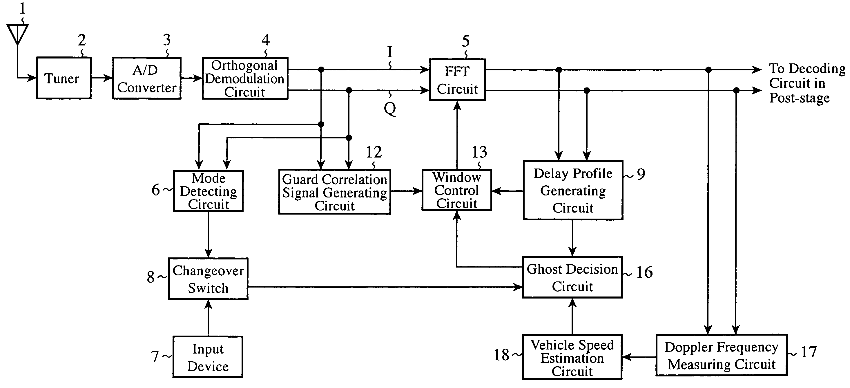
[0061]FIG. 5 is a block diagram showing a configuration of the digital broadcasting receiving apparatus with a channel estimation function of an embodiment 2 in accordance with the present invention. It tries to improve the receiving performance of the digital broadcast by carrying out the window control of the FFT circuit 5, which belongs to the receiving function side of the digital broadcasting, by adding the ghost decision result to the delay profile.

[0062]In FIG. 5, the same components as those of FIG. 1 are designated by the same reference numerals. The configuration of FIG. 5 differs from that of FIG. 1 in that it includes a guard correlation signal generating circuit 12 and a window control circuit 13. The guard correlation signal generating circuit 12 and window control circuit 13 constitute a Fourier transform control section. Here, the description will be omitted of the components with the same reference numerals as those of FIG. 1.

[0063]In the foregoing configuration, ac...

embodiment 3

[0069]FIG. 6 is a block diagram showing a configuration of the digital broadcasting receiving apparatus with a channel estimation function of an embodiment 3 in accordance with the present invention. It tries to improve the receiving performance of the digital broadcast by eliminating the ghosts that will appear and by carrying out the window control of the FFT circuit 5.

[0070]In FIG. 6, the same components as those of FIG. 1 or FIG. 5 are designated by the same reference numerals. The configuration of FIG. 6 differs from that of FIG. 5 in that a ghost eliminating circuit 14 is added, and the accumulator 11 is removed. Here, the description will be omitted of the components with the same reference numerals as those of FIG. 1 or FIG. 5.

[0071]In the foregoing configuration, the ghost eliminating circuit 14 is supplied with the delay profile signal output from the delay profile generating circuit 9 and the ghost decision signal output from the ghost decision circuit 10. According to th...


PUM


Abstract

A delay profile generating circuit 9 generates a delay profile signal. Concerning the delay profile signal, a ghost decision circuit 10 makes a decision as to the presence or absence of ghosts that will appear during traveling of a mobile vehicle in response to a transmission mode signal fed from a changeover switch 8. The delay profile signal and the decision signal about the presence / absence of the ghosts are delivered to a window control circuit 13 via an accumulator 11. The window control circuit 13 sets and controls the FFT window position of an FFT circuit 5 in response to a guard correlation signal fed from a guard correlation signal generating circuit 12 and a signal fed from the accumulator 11.

Description

TECHNICAL FIELD[0001]The present invention relates to a digital broadcasting receiving apparatus with a channel estimation function, which can estimate the conditions of an information transmission line under mobile receiving environments of orthogonal frequency division multiplexing (OFDM) digital broadcasting, and which controls a receiving state of the broadcasting in response to the estimation results.BACKGROUND ART[0002]As a means for estimating conditions of a transmission line of broadcasting information in digital broadcasting reception based on the orthogonal frequency division multiplexing (called “OFDM” from now on) which uses multiple carriers and transmits information discretely, delay profile calculation is known which represents characteristic delayed wave received power against delay time. The delay profile can provide information about a currently receiving incoming path (transmission line) environment. Accordingly, in a multipath environment having delayed waves mi...

Claims


Application Information

Patent Timeline
Patent Type & Authority Patents(United States)
IPC IPC(8): H04L27/06H04L27/28H04L25/08
CPCH04L27/2665H04L27/2678H04L5/0007H04L5/0048H04L25/0212
Inventor TAKEUCHI, MITSURUMORITA, MASAKAZUSAKAGUCHI, TADASHIIDO, JUN
Owner MITSUBISHI ELECTRIC CORP
Learn More