Method and induction furnace for drawing large diameter preforms to optical fibres

a technology of optical fiber and induction furnace, which is applied in the field of graphite induction furnace, can solve the problems of turbulence in making it difficult to control and reducing the flow of conditioning gas. , to achieve the effect of increasing the amount of drawn fiber, reducing the number of times, and reducing the flow of conditioning gas

Inactive Publication Date: 2010-10-19
PIRELLI CAVI E SISTEMI SPA +1
View PDF58 Cites 6 Cited by
  • Summary
  • Abstract
  • Description
  • Claims
  • Application Information

AI Technical Summary

Benefits of technology

[0030]If the diameter of the preform is sufficiently small, the free space in the neck-down zone is quite reduced and turbulence in the flow of conditioning gas may be prevented easier, as suggested by the prior art previously discussed. However, the Applicant has observed that by increasing the diameter of the preform also the free space in the neck-down zone is increased, thus rendering more difficult the control of turbulence in the flow of conditioning gas through the furnace and turbulence caused by unwanted intrusion of ambient atmospheric gases.
[0041]In addition, use of a particular insulating material for a furnace according to the present invention allows improvements in terms of construction, maintenance and constancy of performance of the furnace.

Problems solved by technology

With the aim of developing larger diameter furnaces, the Applicant has however observed some problem associated with a simple scale-up of conventional furnaces, in order to adapt them to receive large diameter preforms.
One problem observed by the Applicant in connection with the heating of large diameter preform in conventional induction furnaces is the turbulence in the conditioning gas and in ambient atmospheric gas entering the furnace.
However, the Applicant has observed that by increasing the diameter of the preform also the free space in the neck-down zone is increased, thus rendering more difficult the control of turbulence in the flow of conditioning gas through the furnace and turbulence caused by unwanted intrusion of ambient atmospheric gases.

Method used


Image

  • Method and induction furnace for drawing large diameter preforms to optical fibres
  • Method and induction furnace for drawing large diameter preforms to optical fibres
  • Method and induction furnace for drawing large diameter preforms to optical fibres

Examples


Embodiment Construction

[0086]Reference will now be made in detail to the present preferred embodiment of the invention, an example of which is illustrated in the accompanying drawings. Wherever possible, the same reference numbers will be used throughout the drawings to refer to the same or like parts.

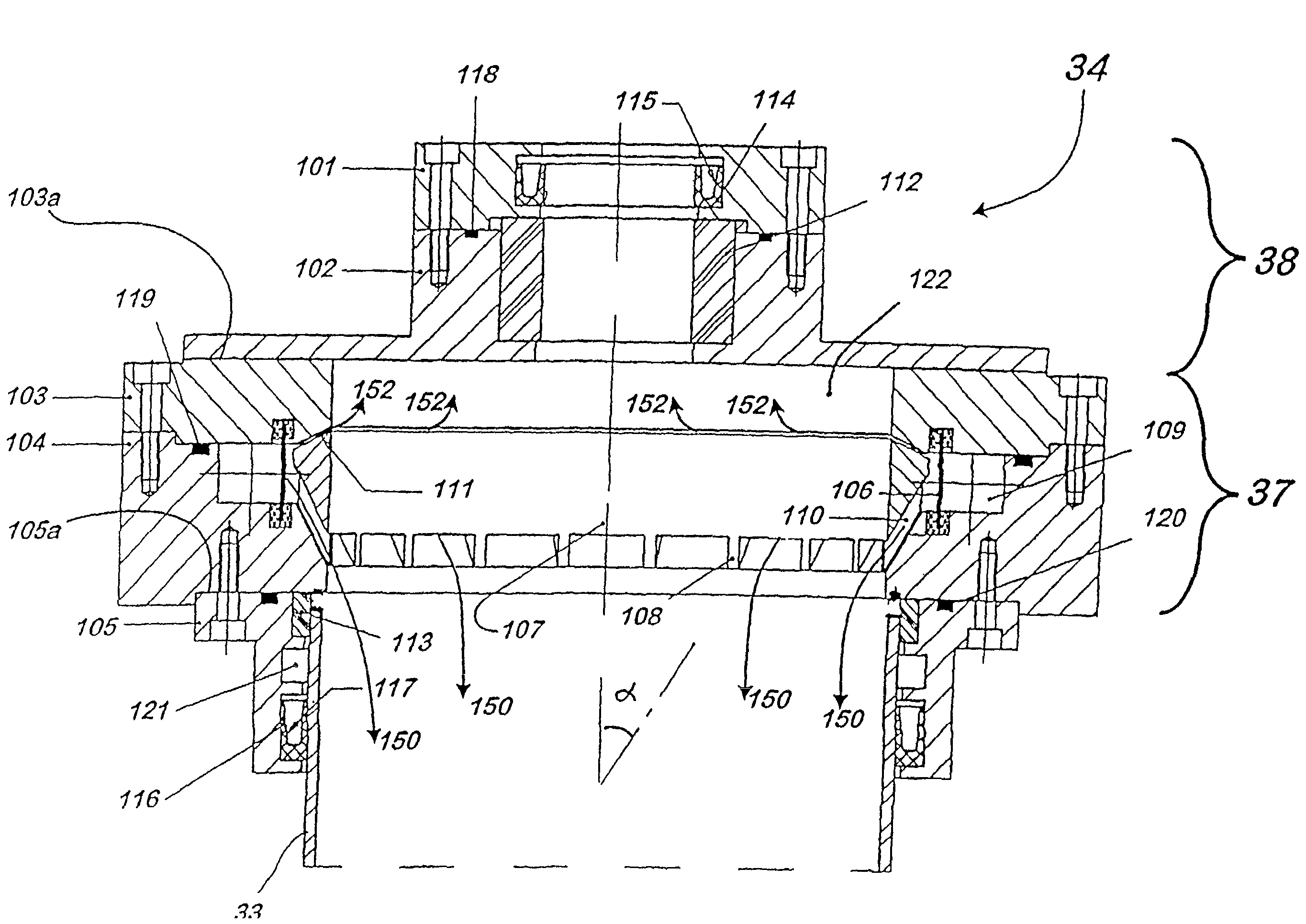
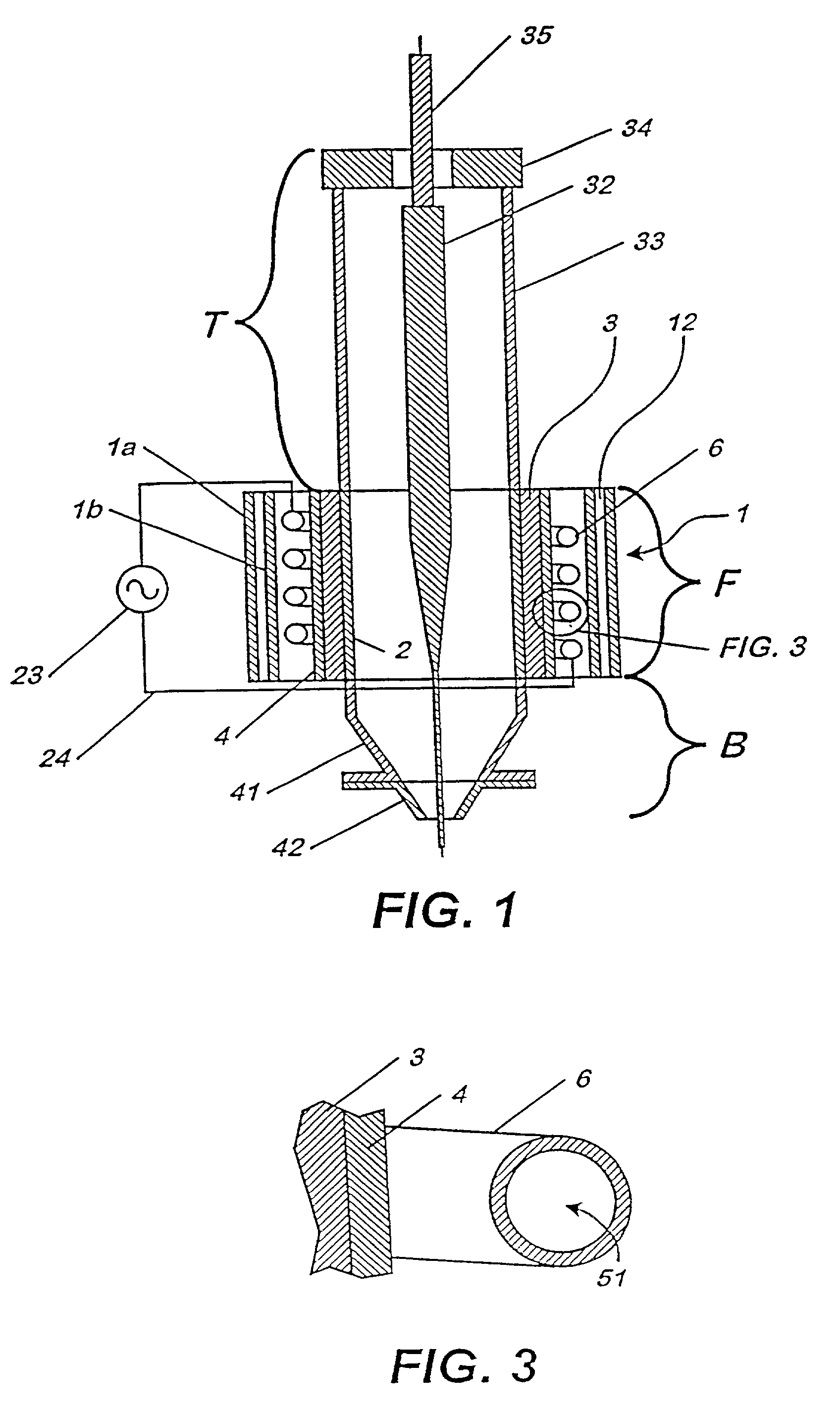
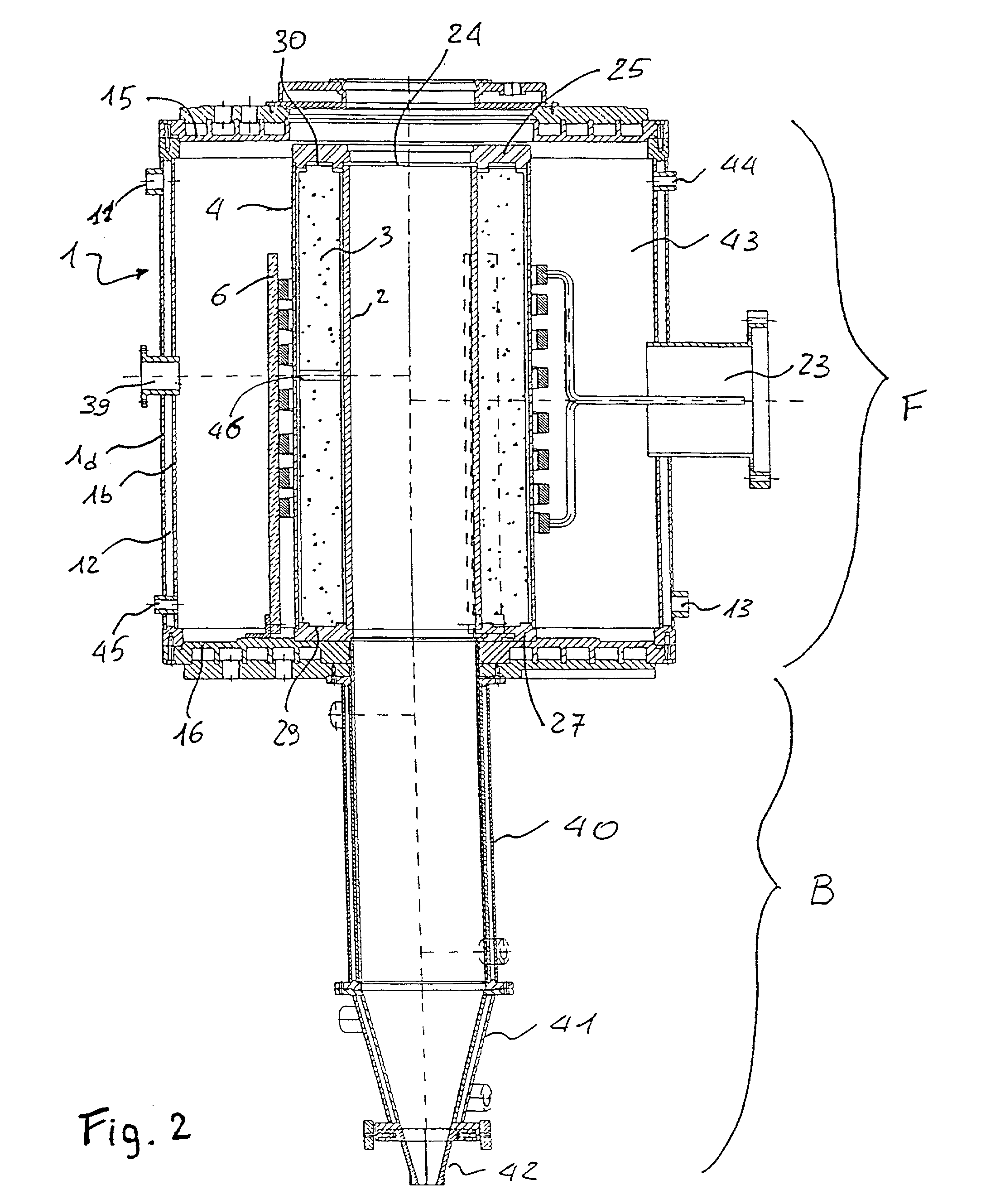
[0087]FIG. 10 schematically depicts a conventional system for drawing an optical fiber 1002 from an optical preform, said system being typically located onto a so-called drawing tower. The drawing system generally comprises a drawing furnace 1001, wherein the bottom of an optical preform is heated at its softening temperature, an apparatus 1003 for measuring the diameter of the drawn fiber 1002, a cooling apparatus 1004 for cooling the fiber before coating it and a coating device 1005 for applying the protective coating onto the fiber. The optical preform is generally connected to moving means for progressively moving the preform downwardly to the heating zone of the furnace while the fiber is being drawn. T...


PUM

PropertyMeasurementUnit
heightaaaaaaaaaa
temperaturesaaaaaaaaaa
inner diameteraaaaaaaaaa

Abstract

An induction furnace capable of drawing large diameter preforms of up to 130 mm is described. The induction furnace has top and bottom chimneys surrounding the entire preform during operation of the furnace with an inert conditioning gas which is introduced into the top chimney and flows downward through the furnace body and bottom chimney without significant turbulence. A distributor ring inside the top chimney redirects flow from a circumferential direction to a downward direction. The top chimney also includes a resilient seal to releasably hold the top of the preform. The bottom chimney has a smoothly decreasing cross-sectional area preventing turbulence at the furnace exit. The furnace insulation is preferably a rigid self-supporting graphite cylinder. A method of drawing large diameter preforms either to an optical fiber or to a preform of smaller diameter using such a furnace is also described.

Description

CROSS REFERENCE TO RELATED APPLICATIONS[0001]This application is a continuation of international application number PCT / EP00 / 04134, filed May 9, 2000, the content of which is incorporated herein by reference, and claims the priority of European Patent Application No. 99109154.7, filed May 10, 1999, and the benefit of U.S. Provisional Application No. 60 / 134,066, filed May 13, 1999, the content of which is incorporated herein by reference.BACKGROUND OF THE INVENTION[0002]1. Field of the Invention[0003]The present invention relates to a furnace for and method of drawing optical fibers and specifically to a graphite induction furnace for drawing optical fibers from large glass preforms and method for drawing optical fiber or smaller diameter preforms from such large-diameter preforms.[0004]2. Description of the Related Art[0005]Furnace designed for drawing optical fibers may be divided into two main categories, defined by the method of heating, which can be conductive heating or inducti...

Claims


Application Information

Patent Timeline
Patent Type & Authority Patents(United States)
IPC IPC(8): C03B37/023C03B37/07C03B37/012C03B37/029H05B6/02H05B6/20
CPCC03B37/0124C03B37/029H05B6/20C03B2205/98C03B2205/96C03B2205/92C03B2205/82Y02P40/57C03B2205/80C03B2205/70C03B2205/64C03B2205/81
Inventor ROBA, GIACOMO STEFANONUTINI, MASSIMOVERONELLI, FRANCO
Owner PIRELLI CAVI E SISTEMI SPA
Why Eureka
Try Eureka