
Combustion control based on a signal from an engine vibration sensor

a technology of vibration sensor and combustion control, which is applied in the direction of electric control, machines/engines, mechanical equipment, etc., can solve the problems of uncontrolled combustion and engine damage, and achieve the effect of not cost prohibitive and improved accuracy

Inactive Publication Date: 2010-10-12
FORD GLOBAL TECH LLC
View PDF12 Cites 24 Cited by
  • Summary
  • Abstract
  • Description
  • Claims
  • Application Information

AI Technical Summary

Benefits of technology

The present invention provides a simple and robust method for controlling the combustion behavior of an internal combustion engine. This is achieved by using a vibration sensor to detect and characterize the combustion behavior. The sensor signal is filtered and processed to obtain an energy factor, which is then used to control engine parameters that affect combustion. The method can be carried out with analog signals and has been found to be particularly useful for controlling knock in spark-ignition engines. The invention also includes a method for feeding back control of combustion based on the energy factor. Overall, the invention provides a simple and effective way to control the combustion behavior of internal combustion engines.

Problems solved by technology

Knock occurs when uncombusted gases ignite prematurely ahead of the flame front causing uncontrolled combustion.
If knock is severe, i.e., a large fraction of the inducted air-fuel charge autoignites and occurs over many cycles, the engine can be damaged.

Method used


Image

  • Combustion control based on a signal from an engine vibration sensor
  • Combustion control based on a signal from an engine vibration sensor
  • Combustion control based on a signal from an engine vibration sensor

Examples


Embodiment Construction

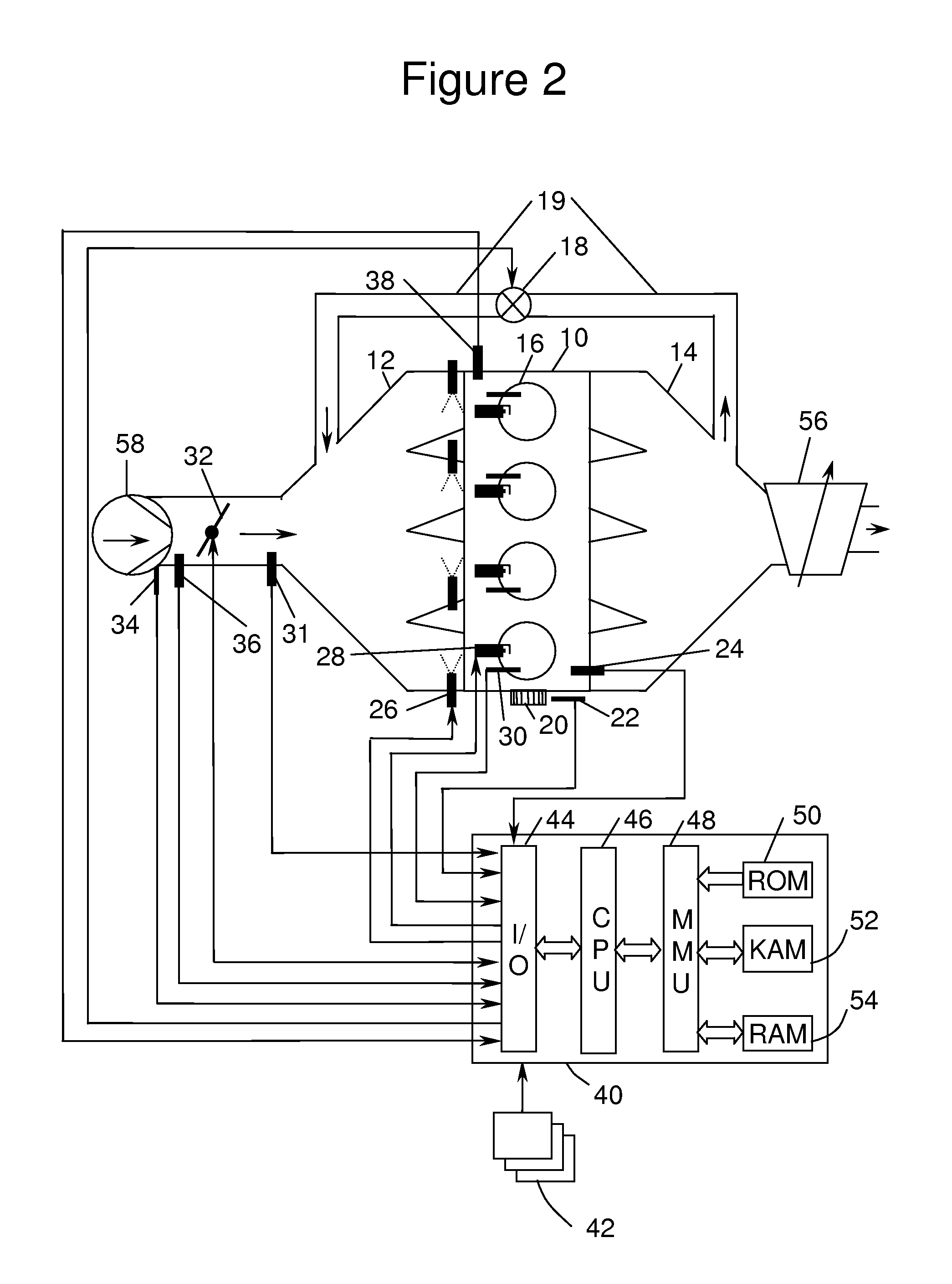
[0027]A 4-cylinder internal combustion engine 10 is shown, by way of example, in FIG. 2. Engine 10 is supplied air through intake manifold 12 and discharges spent gases through exhaust manifold 14. An intake duct upstream of the intake manifold 12 contains a throttle valve 32 which, when actuated, controls the amount of airflow to engine 10. Sensors 34 and 36 installed in intake manifold 12 measure air temperature and mass air flow (MAF), respectively. Sensor 31, located in intake manifold 14 downstream of throttle valve 32, is a manifold absolute pressure (MAP) sensor. A partially closed throttle valve 32 causes a pressure depression in intake manifold 12 compared to the pressure on the upstream side of throttle valve 32. When a pressure depression exists in intake manifold 12, exhaust gases are caused to flow through exhaust gas recirculation (EGR) duct 19, which connects exhaust manifold 14 to intake manifold 12. Within EGR duct 19 is EGR valve 18, which is actuated to control EG...


PUM


Abstract

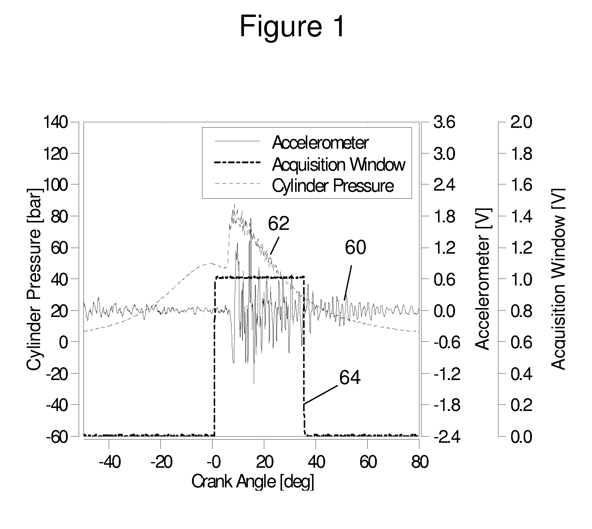
Feedback control of an internal combustion engine is performed based on a signal from a vibration sensor and a crankshaft angle sensor. An energy factor can be computed based on these sensor signals. A vector of energy factor can be computed as a function of crank angle degree over a particular window of engine rotation of interest. Based on the energy factor vector, combustion phasing can be estimated.

Description

FIELD OF THE INVENTION[0001]The invention relates to a method for characterizing the combustion behavior of an internal combustion engine based on the output of an engine vibration sensor and to a control system and a method for feedback control of the combustion of an internal combustion engine which are based on the former method.BACKGROUND OF THE INVENTION[0002]Conventional control systems for injecting fuel into internal combustion engines such as, for example, diesel engines typically operate in an open-loop control circuit. That is to say the injection time and the pulse width of the injection are extracted from permanently predefined characteristic diagrams or table memories which are stored in the engine's electronic control unit. Although such systems exhibit very fast control behavior, they are otherwise not very robust with respect to engine tolerances since the control strategy cannot be adapted in the case of faults. If, for example, the flow characteristics of an injec...

Claims


Application Information

Patent Timeline
Patent Type & Authority Patents(United States)
IPC IPC(8): F02P5/00F02M7/00
CPCF02D35/02F02D35/027F02D35/028G01M15/12F02B1/12F02D23/00F02D41/0052F02D41/402F02M25/0707F02D35/021F02D2041/281F02M26/05
Inventor VIGILD, CHRISTIANTUMELAIRE, CHARLESKARVOUNIS, EVANGELOSROETTGER, DANIELBREWBAKER, THOMASVAN NIEUWSTADT, MICHIELHOPKA, MICHAELBREHOB, DIANA
Owner FORD GLOBAL TECH LLC
Learn More