
Enhanced feedback for plant control

a plant control and enhanced technology, applied in the field of enhanced feedback for plant control, can solve the problems of increasing the delay of successively more accurate higher-order approximations generated by the gerzon procedure, the inability to deal with deviations from the expected plant behaviour, and the inability to deal with deviations

Inactive Publication Date: 2010-07-13
CRAVEN PETER
View PDF13 Cites 9 Cited by
  • Summary
  • Abstract
  • Description
  • Claims
  • Application Information

AI Technical Summary

Benefits of technology

[0025]The present invention provides a method for controlling the behaviour of a plant that combines some of the advantages of both the feedback and predistortion techniques. It is able to correct both the known and the unknown nonlinearities of the plant, with the advantage that it is only the unknown nonlinearities (or other deviations from assumed behaviour) that have the potential to send the system unstable. The simulated signal, which is used to generate the difference signal, is generated after the feedback is applied to the input and is therefore affected by it.
[0027]Preferably, the step of generating the simulated signal further comprises simulating the step of deriving the plant feedback signal. In this way, any sampling or modification of the output signal to generate a feedback signal may be taken into account by the simulation to provide an accurate difference signal in dependence on which the input signal is modified.
[0028]Preferably, the step of modifying the input signal by feedback reduces the effect on the plant output of a deviation in actual behaviour of the plant from the assumed behaviour of the plant over a predetermined operating frequency range. In this way, stable operation of the plant may be maintained over a particular chosen frequency range.
[0031]The simulation may be based on a predetermined characterisation of the plant at start-up. Alternatively, or additionally, the simulation may be performed responsively to factors influencing the behaviour of the plant or to the behaviour of the plant itself. In this way, dynamic adaptive control of the simulation can be achieved.
[0041]Preferably, the modifying unit is adapted to modify the input signal to reduce the effect on the plant output signal over a predetermined operating frequency range of a deviation in actual behaviour of the plant from the assumed behaviour of the plant.
[0050]As will be appreciated, the feedback controller according to the present provides for robust control of a plant, combining advantages of predistortion and feedback techniques and able to correct for both known and unknown nonlinearities, which would cause a conventional control system to go unstable. The controller may be designed and fitted to a range of standalone devices and systems. Alternatively, the controller may form an integral part of a feedback-controlled device in pre-packaged form.

Problems solved by technology

The classic problem of feedback design is to apply enough feedback for the desired performance improvement while keeping the system stable.
Predistortion can correct for known nonlinearity of the plant and does not have stability problems, but is powerless to deal with deviations from the expected plant behaviour.
Feedback can correct both known and unknown nonlinearity of the plant, and can correct other deviations from the expected behaviour, but may be sent unstable if the nonlinearities or other deviations are too large.
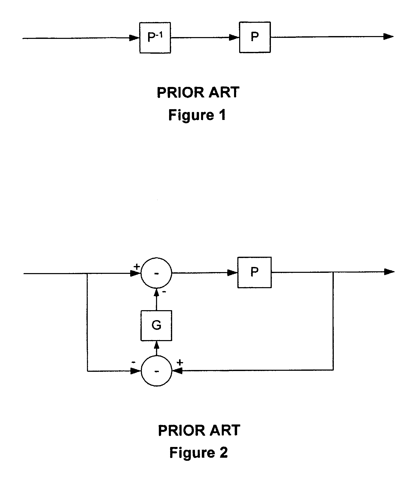
This technique can be extremely effective when it works, but in some cases P may not have a causal inverse.
Indeed, successively more accurate higher-order approximations generated by the Gerzon procedure incur more and more delay.
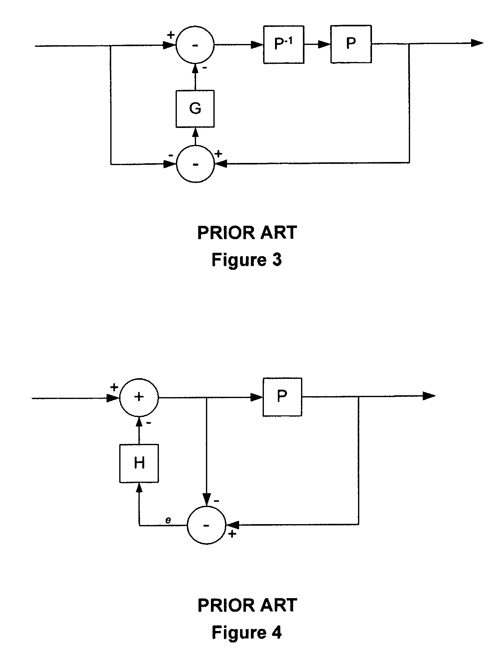
Thus, with the delay introduced by the Gerzon predistortion, the system shown in FIG. 3 may be unable to support sufficient feedback to correct adequately the unknown disturbances that are not corrected by P−1.
To restate the problem, the plant P may itself have a delay, and there is nothing that can be done about that.
The unfortunate consequence of the system shown in FIG. 3 is that P−1 may further increase the delay.

Method used


Image

  • Enhanced feedback for plant control
  • Enhanced feedback for plant control
  • Enhanced feedback for plant control

Examples


Embodiment Construction

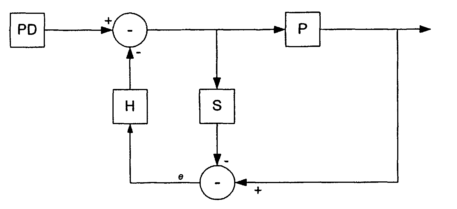
[0091]The present invention provides for a feedback correction signal to be obtained by taking the difference between the output of the plant and the output of a simulator that models the plant. In the simplest embodiment of the invention, a simulator S models known aspects of the plant P, and the feedback modifies the input to the plant in response to the difference between the output of the plant and the output of the simulator. This is shown in FIG. 5, which is to be compared with FIG. 4.

[0092]In FIG. 5, the subtraction node at the bottom of the figure extracts the said difference as an error signal e. In this way, to the extent that S models P accurately, e will be zero. Even if e receives a perturbation because of noise or because of mismatch between S and P, and this perturbation is fed through H thereby providing a perturbation to the input u of the plant P, the perturbation to the output of P will be substantially balanced by a similar perturbation to the output of S. Theref...


PUM


Abstract

A method and system for controlling the behavior of a plant having an input and an output by enhanced feedback. A simulation input signal is derived from an input to be applied to the plant and a simulated signal is generated by simulating an aspect of an assumed behavior of the plant in dependence on the simulation input signal. The simulated signal is subtracted from a plant feedback signal which is derived from an output of the plant and the resulting difference signal is used to modify the input signal by feedback prior to deriving a plant input signal. The simulation may take into account derivation of the plant feedback signal and the input signal is typically modified so as to reduce the effect on the output signal of a deviation in actual behavior of the plant from the assumed behavior of the plant over a predetermined operating frequency range.

Description

FIELD OF THE INVENTION[0001]The present invention relates to use of feedback for controlling a device or system characterised generically as a plant.BACKGROUND TO THE INVENTION[0002]Many techniques are known in many technical fields for controlling the response or behaviour of a device or system. In Control Theory literature, the term “plant” is generally used to refer to such a device whose behaviour we are trying to control. In this context, a plant could be anything from the tiny armature that carries the cutting stylus of an LP disc-cutting head to a space-rocket whose motion we are sensing and trying to control by sending instructions to its motors. Other examples include the power output stage of an amplifier and a mechanical actuator. Indeed, the concept can be extended to include control of a complete factory or chemical processing plant.[0003]A substantial part of the control theory literature addresses the control of systems, for example biological systems, in which the ef...

Claims


Application Information

Patent Timeline
Patent Type & Authority Patents(United States)
IPC IPC(8): G05B13/02
CPCG05B13/042G05B13/048G05B17/02
Inventor CRAVEN, PETER
Owner CRAVEN PETER
Learn More