
Ring type network system including a function of setting up a path

a network system and function technology, applied in the field of ring-type network systems, can solve the problems of extra standby resources and the inability to restore the ring

Inactive Publication Date: 2010-09-28
FUJITSU LTD
View PDF10 Cites 2 Cited by
  • Summary
  • Abstract
  • Description
  • Claims
  • Application Information

AI Technical Summary

Benefits of technology

The present invention provides a technology for setting up a path that can reduce the use of standby resources for ring protection in a network system. The technology involves a node that stores information about physical links and virtual links in a network, and a processing unit that receives a signaling message for setting up a path. The processing unit analyzes the path route information and the physical link information to select the physical links that form the path. The technology ensures that paths passing through the same ring can be set up to the greatest degree, reducing the use of standby resources for ring protection.

Problems solved by technology

In this case, a standby path must be set up in each ring, and therefore such a problem arises that extra standby resources are needed.
Further, in the case of BLSR (Bidirectional Line Switched Ring) ring as a second ring protection technology, on the route coming and going between the rings R1, R2, if a fault occurs in the node N5 or the node N6, resulting in a problem where the ring can not be restored.

Method used


Image

  • Ring type network system including a function of setting up a path
  • Ring type network system including a function of setting up a path
  • Ring type network system including a function of setting up a path

Examples


operational example

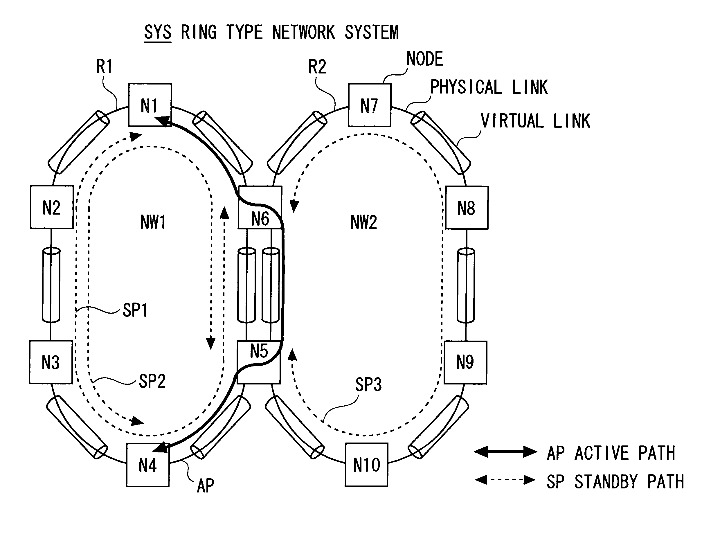
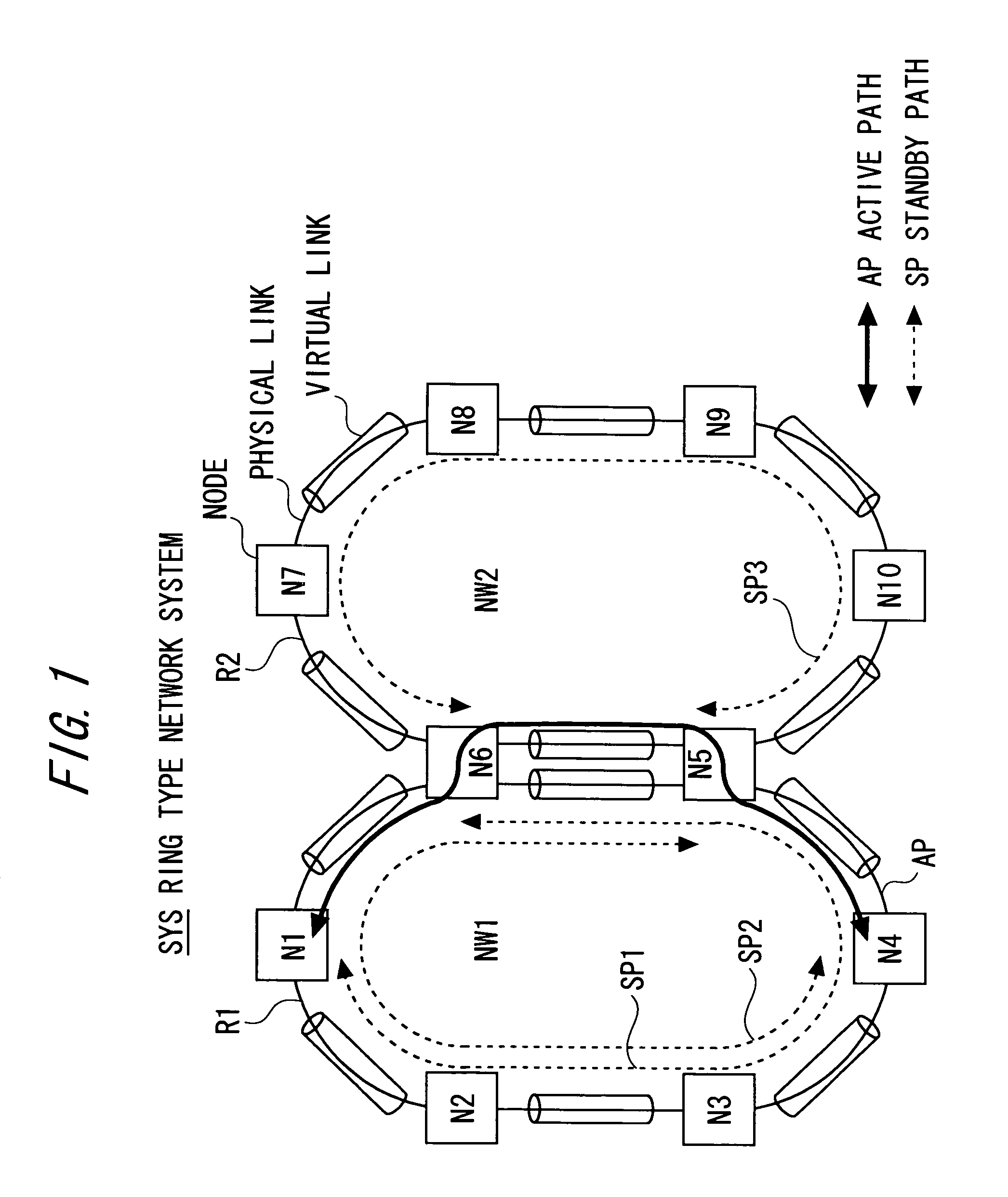
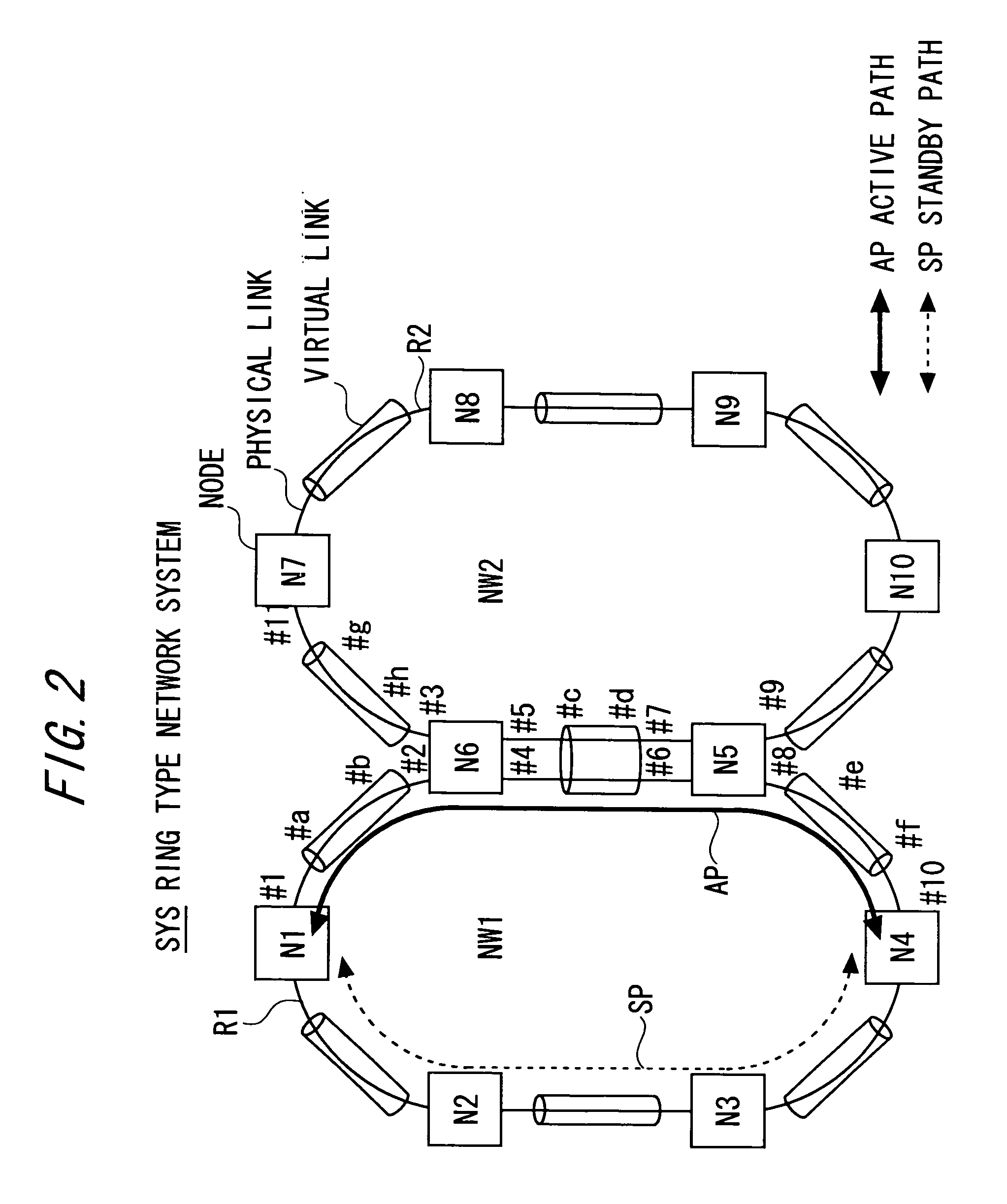
[0041]Next, an operational example in the ring type network system SYS in one embodiment of the present invention will be explained with reference to FIGS. 2 through 8 in combination. FIG. 8 is a flowchart showing a processing procedure (S1-S9) in each node.

[0042]Exemplified herein is, in the ring type network system SYS illustrated in FIG. 2, a case of setting up a path (Active Path) AP extending from the node (originating node) N1 to the node (terminating node) N4 that belong to the first ring network NW1 on the first ring R1.

[0043]To start with, in the node N1, the route calculation unit 10 calculates the route of the setup target path and transfers the route information (path route information) to the message processing unit 8.

[0044]The message processing unit 8 sets (stores), in the signaling message (path setup message), the port number (output port numbers) #b, #d, #f of the virtual links on the route, the port number (output port number) #1 of the physical link selected in r...

modified example

[0053]The processes in one embodiment discussed above are provided as a program executable by a computer and can be provided through storage medium such as a CD-ROM and a flexible disc and further via a communication line. Further, the respective processes in one embodiment discussed above can be also carried out in a way that selects and combines an arbitrary plural number of processes or all the processes.


PUM


Abstract

A node for configuring a ring type network system in such a mode that a plurality of physical links belonging to difference rings exists between nodes opposite to each other, has a storage unit stored with link associated information representing an associated relationship between ports of physical links and a port of a virtual link virtually set up to at least one physical link, ring configuration information representing a paired relationship of the ports of the physical links configuring the different ring, port numbers of both ends of the physical link and port numbers of both ends of the virtual link, and a processing unit executing a process of transmitting, to other nodes, such information that one virtual link is associated with the plurality of physical links belonging to the different ring, and setting up, when receiving a signaling message for setting up a path, the path passing through the same ring on the basis of pass route information in the message and the storage information stored in the storage unit.

Description

BACKGROUND OF THE INVENTION[0001]The present invention relates generally to a ring type network system in such a mode that a plurality of physical links belonging to difference rings exists between two nodes opposite to each other, and more particularly to a ring type network system having a function of setting up a path (active path) capable of restraining use of standby resources for ring protection.[0002]In a SONET (Synchronous Optical Network) / SDH (Synchronous Digital Hierarchy) network as a ring type network system, there is a method by which topology information is organized by advertising (broadcasting) virtual link information in a way that utilizes a routing protocol OSPF-TE (Open Shortest Path First-Traffic Engineering) (defined in RFC3630), and a path is set up based on a result of calculating a route of the path in a way that utilizes a signaling protocol RSVP-TE (Resource Reservation Protocol-Traffic Engineering) (defined in RFC3209, RFC3473) etc.[0003]In the prior art,...

Claims


Application Information

Patent Timeline
Patent Type & Authority Patents(United States)
IPC IPC(8): H04L12/28H04L12/56H04L12/42
CPCH04L12/437H04L45/00H04L45/22H04L45/28H04J3/085H04J2203/0053H04L45/247H04L45/76
Inventor FUJII, YASUKIMIYAZAKI, KEIJIKANO, SHINYANAGATA, AKIRA
Owner FUJITSU LTD
Learn More