Resistance memory with tungsten compound and manufacturing
a technology of resistance memory and tungsten compound, which is applied in the field of memory devices, can solve the problems of copper bottom electrode complicating the erasure of memory cells, relative large memory cell size, and large memory cell siz
- Summary
- Abstract
- Description
- Claims
- Application Information
AI Technical Summary
Benefits of technology
Problems solved by technology
Method used
Image
Examples
first embodiment
[0099]FIGS. 25-28 illustrate a manufacturing method in accordance with a first embodiment, the manufacturing method resulting in forming the memory device 2400 illustrated in FIG. 24.
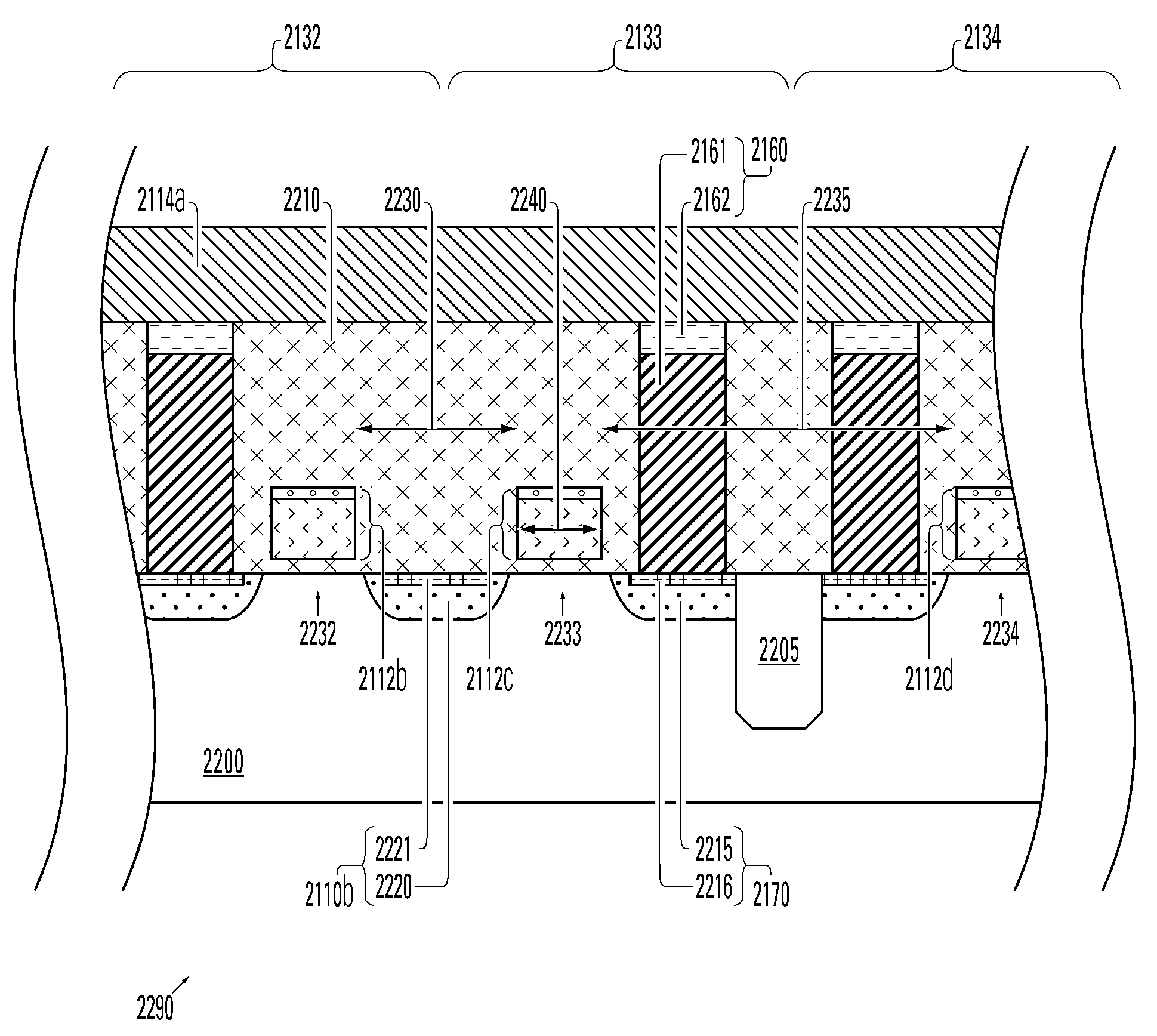
[0100]FIG. 25 illustrates a first step of providing a subassembly including the periphery region 2420 and a memory cell region 2500 on the substrate 2200.
[0101]The memory cell region 2500 includes conductive plugs 2520, 2530, and 2540 each coupled to drain regions of respective access transistors 2232, 2233, and 2234. The plugs 2520, 2530, and 2540 comprise tungsten and extend to the top surface 2460 of dielectric 2210. The top surface 2460 can be formed by example, by a Chemical Mechanical Polishing CMP step after the formation of the plugs 2450, 2520, 2530, 2540 in vias in the dielectric 2210.
[0102]Next, a layer of photoresist 2600 is formed on the periphery region 2420 of the structure illustrated in FIG. 25, resulting in the structure illustrated in FIG. 26. The photoresist 2600 has a thickness 2610...
second embodiment
[0107]FIGS. 29-32 illustrate a manufacturing method in accordance with a
[0108]A dielectric layer 2900 is formed on the top surface 2460 of the dielectric 2210 of the structure illustrated in FIG. 25, and a layer of photoresist 2910 is formed on the portion of the dielectric layer 2900 overlying the logic portion 2420, resulting in the structure illustrated in FIG. 29.
[0109]Next, the dielectric layer 2900 is etched using the photoresist 2910 as a mask, thereby exposing the top surface 2460 of the dielectric 2210 in the memory cell region 2500, resulting in the structure illustrated in FIG. 30.
[0110]Next, an oxygen plasma strip is performed to form the memory portions 2720, 2730, and 2740 from the tungsten material of the plugs 2520, 2530, and 2540 and a wet strip process removes any remaining photoresist 2910, resulting in the structure illustrated in FIG. 31.
[0111]Next, an optional post furnace oxidation step is performed on the structure illustrated in FIG. 31. Because the plug 245...
third embodiment
[0113]FIGS. 33-36 illustrate a manufacturing method in accordance with a
[0114]FIG. 33 illustrates a first step of providing a sub-assembly including the periphery region 2420 and a memory cell region 3300 on the substrate 2200.
[0115]The memory cell region 3300 includes conductive plugs 2520, 2530, and 2540 each coupled to the drain regions of respective access transistors 2232, 2233, and 2234. The memory cell region 3300 also includes a common source line 3310 coupled to the common source region of the access transistors 2232, 2233, the common source line 3310 extending in a direction into and out of the cross-section illustrated in FIG. 33.
[0116]The plugs 2450, 2520, 2530, 2540 and line 3310 comprise tungsten and extend to the top surface 2460 of dielectric 2210. The top surface 2460 can be formed, for example, by a Chemical Mechanical Polishing CMP step after the formation of the plugs 2450, 2520, 2530, 2540 and line 3310 in the dielectric 2210.
[0117]Next, a layer of photoresist i...
PUM
 Abstract
Description
Claims
Application Information
 - R&D
- Intellectual Property
- Life Sciences
- Materials
- Tech Scout
- Unparalleled Data Quality
- Higher Quality Content
- 60% Fewer Hallucinations
Browse by: Latest US Patents, China's latest patents, Technical Efficacy Thesaurus, Application Domain, Technology Topic, Popular Technical Reports.
© 2025 PatSnap. All rights reserved.Legal|Privacy policy|Modern Slavery Act Transparency Statement|Sitemap|About US| Contact US: help@patsnap.com


