
Microfabricated integrated DNA analysis system

a microfabricated and integrated technology, applied in the field of microfabricated systems and genome sequencing methods, can solve the problems of refractory steps to miniaturization and integration, unable to meet the needs of microfabricated technology, and the minimum quantity of materials prepared by such robotic technology is orders of magnitude more than required, and achieves significant cost, time and space saving, and easy automation

Active Publication Date: 2010-09-21
RGT UNIV OF CALIFORNIA
View PDF148 Cites 181 Cited by
  • Summary
  • Abstract
  • Description
  • Claims
  • Application Information

AI Technical Summary

Benefits of technology

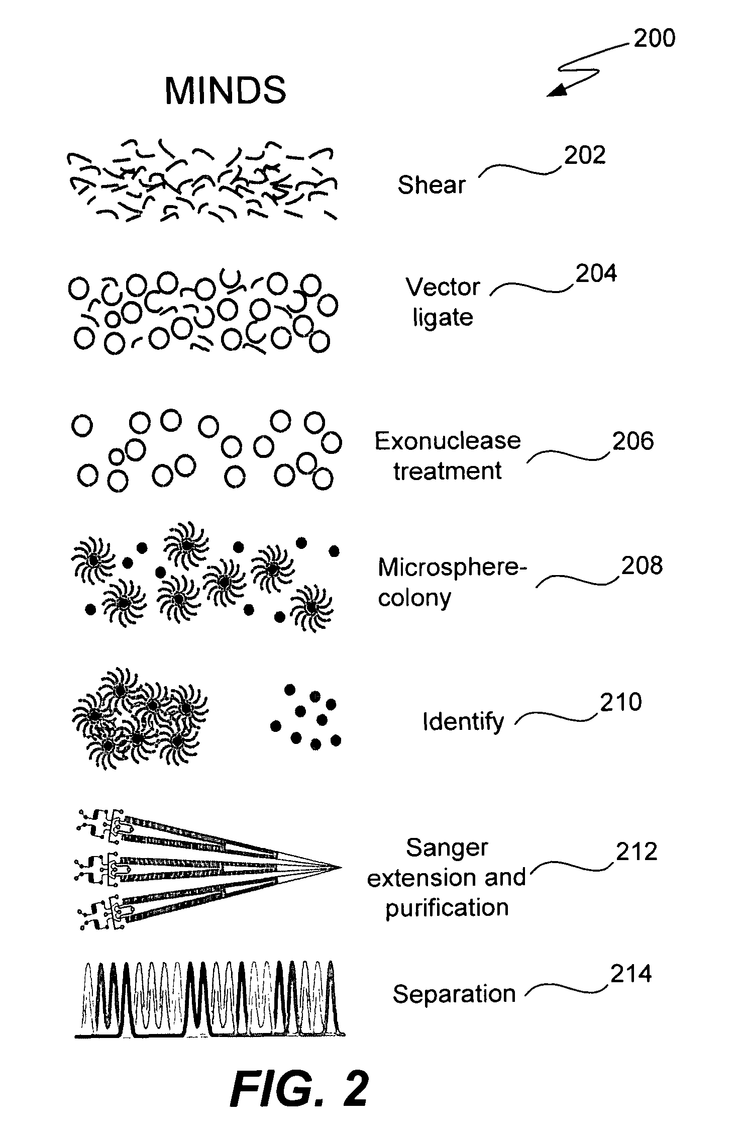
[0029]The invention can include one or more of the following advantages. The laborious bacterial manipulations required by shotgun genome sequencing are replaced with easily automated and integrated in vitro steps. As such, millions of manual or robotic colony picking operations are eliminated. All fluidic and temperature control structures necessary to produce, purify, and separate sequencing extension fragments are integrated on a microfabricated device. Significant cost, time, and space savings can be achieved. Other genetic analysis techniques can be performed.

Problems solved by technology

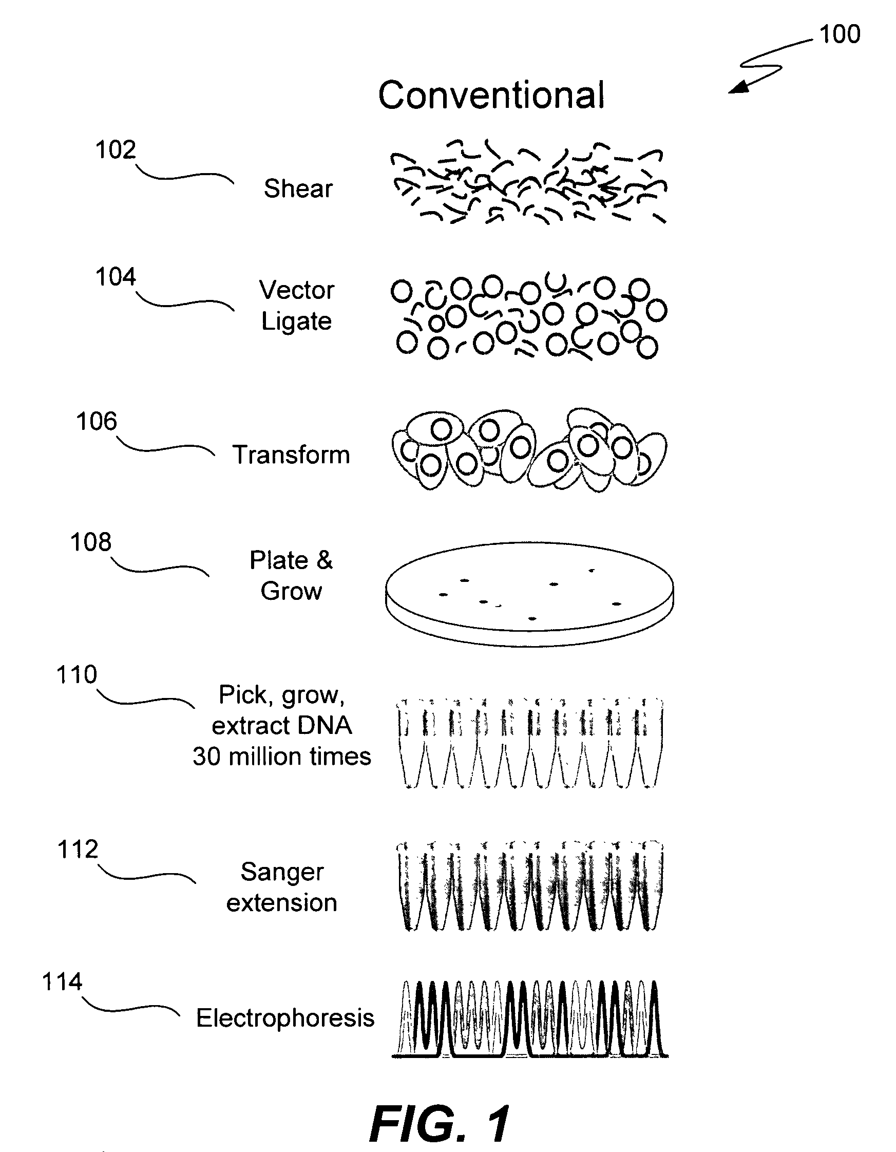
The plate and grow (step 108), and the pick, grow and extract steps (step 110), however, are problematic.
These steps have remained refractory to miniaturization and integration.
However, this is a problem because no less than 30 million colonies must be picked and grown to produce a sequencing template for a genome.
Furthermore, the minimum quantities of materials prepared by such robotic technologies are orders of magnitude more than that required by modern microfabricated CE analysis systems.

Method used


Image

  • Microfabricated integrated DNA analysis system
  • Microfabricated integrated DNA analysis system
  • Microfabricated integrated DNA analysis system

Examples


Embodiment Construction

[0042]Reference will now be made in detail to some specific embodiments of the present invention including the best modes contemplated by the inventor for carrying out the invention. Examples of these specific embodiments are illustrated in the accompanying drawings. While the invention is described in conjunction with these specific embodiments, it will be understood that it is not intended to limit the invention to the described embodiments. On the contrary, it is intended to cover alternatives, modifications, and equivalents as may be included within the spirit and scope of the invention as defined by the appended claims.

[0043]In the following description, numerous specific details are set forth in order to provide a thorough understanding of the present invention. The present invention may be practiced without some or all of these specific details. In other instances, well known process operations have not been described in detail in order not to unnecessarily obscure the presen...


PUM

PropertyMeasurementUnit
diameteraaaaaaaaaa
diameteraaaaaaaaaa
diameteraaaaaaaaaa

Abstract

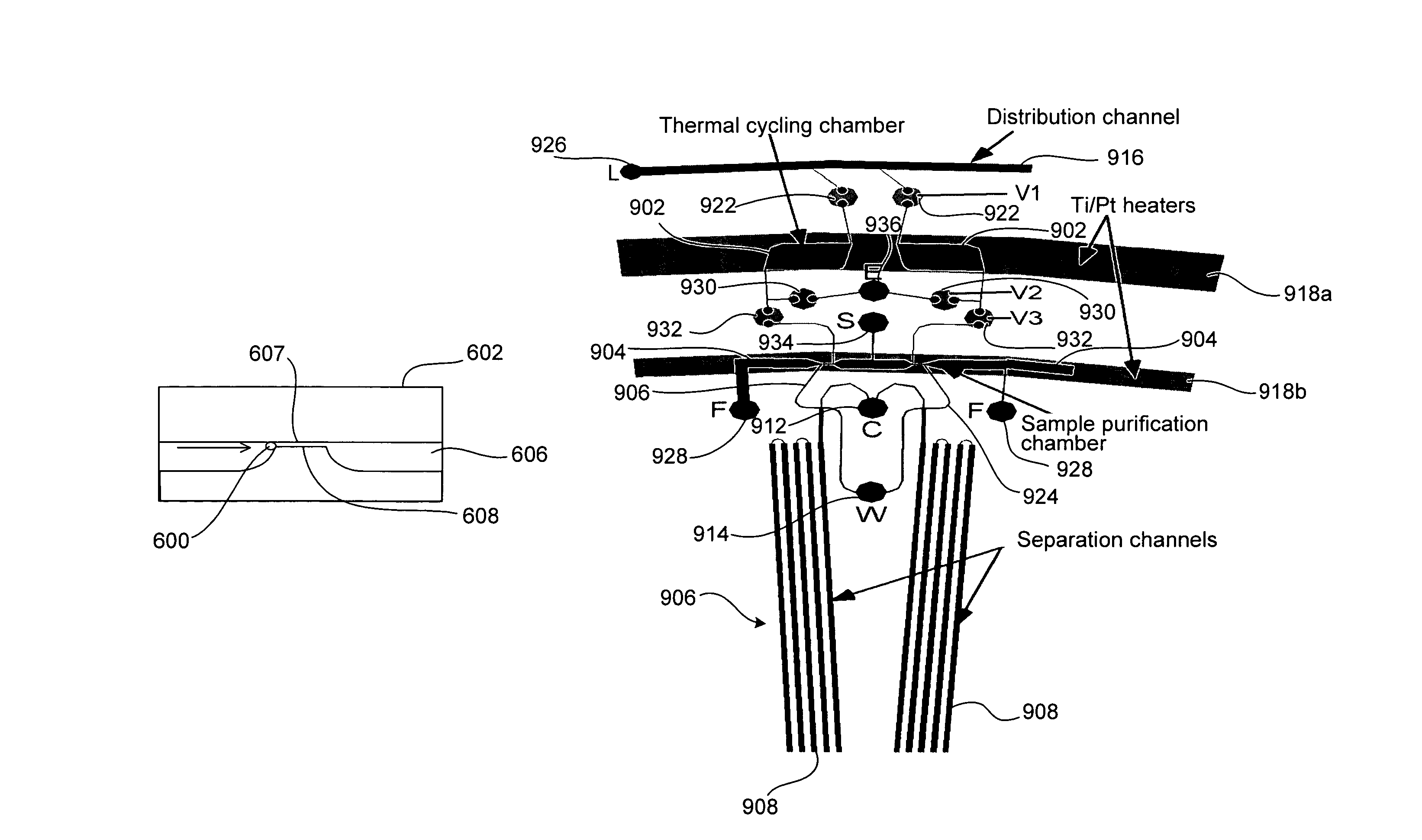
Methods and apparatus for genome analysis are provided. A microfabricated structure including a microfluidic distribution channel is configured to distribute microreactor elements having copies of a sequencing template into a plurality of microfabricated thermal cycling chambers. A microreactor element may include a microcarrier element carrying the multiple copies of the sequencing template. The microcarrier element may comprise a microsphere. An autovalve at an exit port of a thermal cycling chamber, an optical scanner, or a timing arrangement may be used to ensure that only one microsphere will flow into one thermal cycling chamber wherein thermal cycling extension fragments are produced. The extension products are captured, purified, and concentrated in an integrated oligonucleotide gel capture chamber. A microfabricated component separation apparatus is used to analyze the purified extension fragments. The microfabricated structure may be used in a process for performing sequencing and other genetic analysis of DNA or RNA.

Description

CROSS REFERENCE TO RELATED APPLICATIONS[0001]This application claims priority under 35 U.S.C. 119(e) from Provisional U.S. Patent Application Ser. No. 60 / 576,102, filed Jun. 1, 2004, entitled “MICROBEAD INTEGRATED DNA ANALYSIS SYSTEM (MINDS)”, which is incorporated herein by reference.STATEMENT REGARDING FEDERALLY SPONSORED RESEARCH[0002]This invention was made with government support under Grant Numbers AI056472, CA77664, and HG001399 awarded by the National Institute of Health. The government has certain rights in the invention.BACKGROUND[0003]1. Field of Invention[0004]The present invention relates to microfabricated and microfluidic structures. In one example, the present invention relates to a microfabricated system and method for genome sequencing.[0005]2. Description of Related Art[0006]The genome of an organism is defined by the DNA (deoxyribonucleic acid) or, for some viruses, the RNA (ribonucleic acid) of the organism. Genome sequencing is figuring out the order of the nuc...

Claims


Application Information

Patent Timeline
Patent Type & Authority Patents(United States)
IPC IPC(8): C12M1/00C12M1/34C12M3/00B01L3/00B01L7/00C12Q1/68
CPCB01L3/50273B01L3/502753C12Q1/686C12Q1/6869B01L7/52B01L2200/10B01L2200/147B01L2300/0803B01L2300/0864B01L2300/087B01L2300/0874B01L2300/0887B01L2300/1827B01L2400/0415B01L2400/0421B01L2400/0633C12Q2565/518C12Q2537/143C12Q2565/629C12M1/34C12Q1/6806G01N33/48
Inventor MATHIES, RICHARD A.BLAZEJ, ROBERTLIU, CHUNGKUMARESAN, PALANIYEUNG, STEPHANIE H. I.
Owner RGT UNIV OF CALIFORNIA
Learn More