Eureka AIR delivers breakthrough ideas for toughest innovation challenges, trusted by R&D personnel around the world.

Developing member and electrophotographic image forming apparatus

a technology of developing member and electrophotographic image, which is applied in the direction of electrographic process, application, instruments, etc., can solve the problems of prone to fogging and insufficient prevention of fogging in high temperature and high humidity environment, and achieve the effect of high reliability

Active Publication Date: 2010-09-21
CANON KK
View PDF11 Cites 54 Cited by
  • Summary
  • Abstract
  • Description
  • Claims
  • Application Information

AI Technical Summary

Benefits of technology

[0014]Therefore, an object of the present invention is to provide a developing member having high reliability, which can simultaneously inhibit the occurrence of fogging in a high temperature and high humidity environment and the occurrence of ghosts in a low temperature and low humidity environment. Another object of the present invention is to provide an electrophotographic image forming apparatus using the developing member.

Problems solved by technology

Therefore, fogging in a high temperature and high humidity environment is not sufficiently prevented in some cases.
Thus, sufficient frictional chargeability cannot be obtained, thus fogging is liable to occur.

Method used

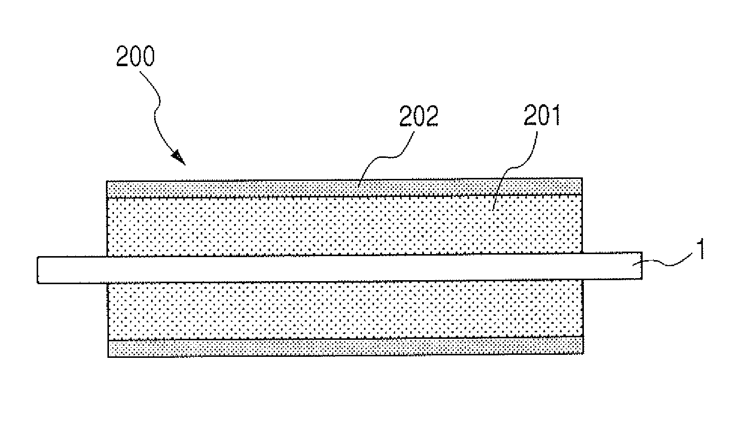
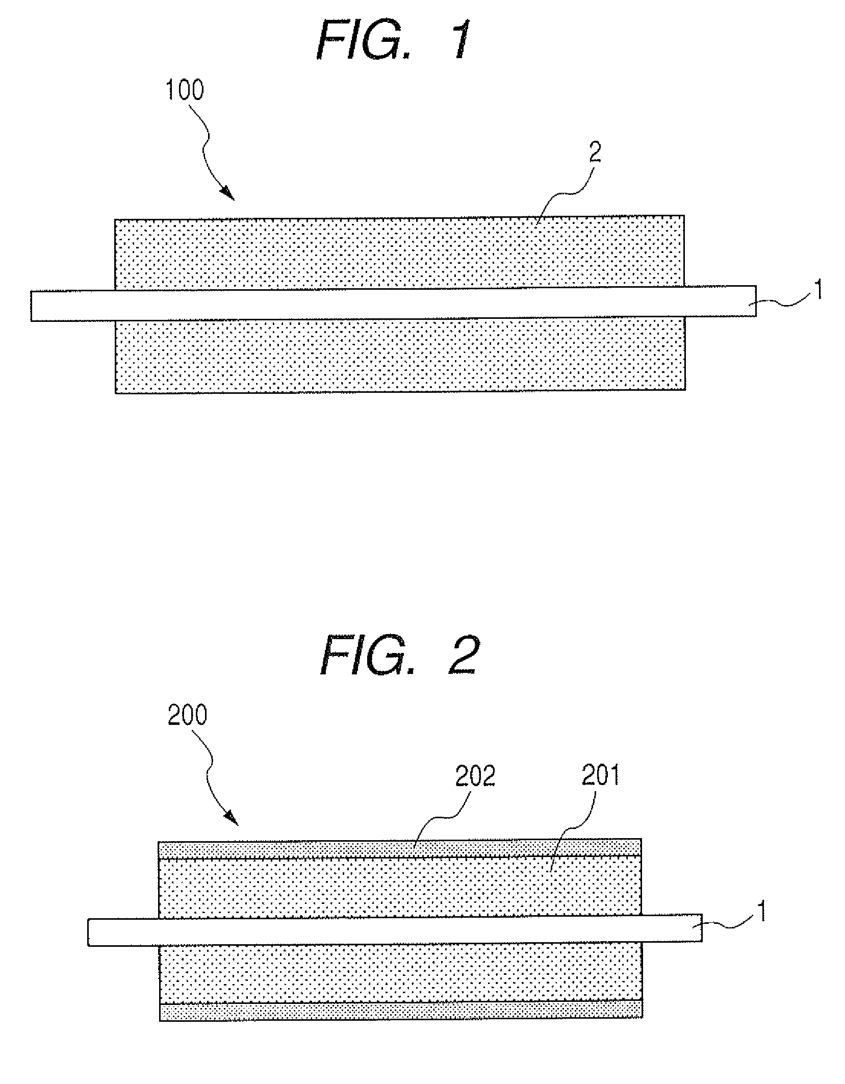
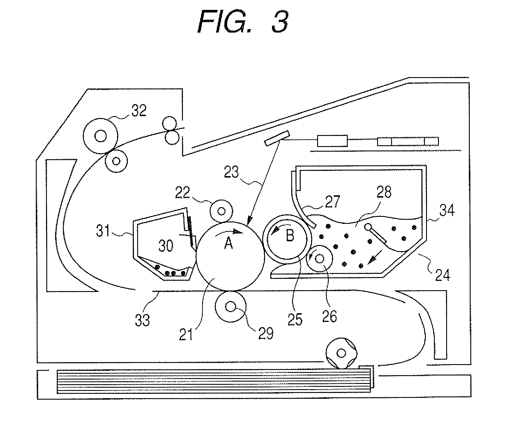

Image

  • Developing member and electrophotographic image forming apparatus
  • Developing member and electrophotographic image forming apparatus
  • Developing member and electrophotographic image forming apparatus

Examples


example 1

[0106]A core bar (mandrel) with an outside diameter of 8 mm was installed in a cylindrical die with an inside diameter of 16 mm so as to be concentrically arranged with the die. Subsequently, a liquid conductive silicone rubber (manufactured by Dow Corning Toray Silicone Co., Ltd., an ASKER-C hardness of 40°, and a volume resistivity of 1×10⁷ Ω·cm) was injected as a material for forming an elastic layer into the cylindrical die. After that, it was placed in an oven at 130° C. and then heated and molded for 20 minutes. After removing the molded product from the die, secondary vulcanization was carried out in an oven at 200° C. for 4 hours, thereby forming an elastic layer with a thickness of 4 mm on the periphery of the core bar.

[0107]Next, the following materials were mixed stepwise in a methyl ethyl ketone solvent and allowed to react with each other at 80° C. for 3 hours under a nitrogen atmosphere. Consequently, a polyether polyol prepolymer (1) with a weight-average molecular we...

example 2

[0115]A core bar covered with an elastic layer was prepared in the same manner as in Example 1.

[0116]A coating fluid for forming a resin layer was prepared as follows.

[0117]First, the following materials were mixed stepwise in a methyl ethyl ketone solvent and then allowed to react with each other at 80° C. for 3 hours under a nitrogen atmosphere. Consequently, a polyether polyol prepolymer (2) with a weight-average molecular weight Mw of 6,800 and a hydroxyl value of 43 was obtained.[0118]Polytetramethylene glycol (trade name: PTG650SN, manufactured by Hodogaya Chemical Co., Ltd.): 100 parts by mass[0119]Trimethylol propane (manufactured by Mitsubishi Gas Chemical Company, INC): 3 parts by mass[0120]Isophorone diisocyanate (manufactured by Aldrich Co., Ltd.): 30 parts by mass

[0121]Next, the following raw materials were mixed and methyl ethyl ketone was then added so as to be in a solid content of 28% by mass. The resulting product was used as a raw material liquid for the formation...

example 3

[0127]A developing roller of Example 3 was produced in the same manner as in Example 2 except that the non-reactive silicone compound No. 2, which was used for preparing the coating fluid for forming the resin layer as the outermost layer, was replaced with the non-reactive silicone compound No. 3; and the mixing amount thereof was changed to 0.5 parts by mass.


PUM

PropertyMeasurementUnit
relative humidityaaaaaaaaaa
temperatureaaaaaaaaaa

Abstract

A developing member is provided which is capable of forming a high-quality image by simultaneously solving the problem of fogging in a high temperature and high humidity environment and the problem of ghosts in a low temperature and low humidity environment. The developing member includes a mandrel and a resin layer formed on the periphery of the mandrel, and has an outermost surface layer containing a non-reactive silicone compound. The non-reactive silicone compound satisfies the following requirements: (A) a copolymer of silicone and polyoxyethylene; (B) a specific gravity (25° C.) d of 0.99≦d≦1.03; and (C) a solubility in water (25° C.) of less than 0.1% by mass.

Description

BACKGROUND OF THE INVENTION[0001]1. Field of the Invention[0002]The present invention relates to a developing member such as a developing roller used in an electrophotographic image forming apparatus such as a copying machine or a laser printer, and to an electrophotographic image forming apparatus using the developing member.[0003]2. Description of the Related Art[0004]Conventionally, a pressure-developing method has been known as one of the developing methods employed in electrophotographic apparatuses such as copying machines, printers, and facsimile receivers. The pressure-developing method uses a developer of a nonmagnetic toner component and attaches the developer to a latent image on a photosensitive drum to visualize the latent image.[0005]The pressure-developing method has been used in a wide variety of applications because of its advantages such as: magnetic material is not required; the apparatus can be made simple or compact with ease; and a developer can be made up as a...

Claims


Application Information

Patent Timeline
Patent Type & Authority Patents(United States)
IPC IPC(8): B29D22/00
CPCG03G15/0818Y10T428/1393Y10T428/1355Y10T428/31663G03G9/00G03G15/00G03G15/06
Inventor NAKAMURA, MINORUYAMAMOTO, ARIHIROYAMADA, MASAKIKURACHI, MASAHIRO
Owner CANON KK
Why Eureka
Eureka Blog
Learn More