
System for analyzing eye responses to automatically track size, location, and movement of the pupil

a technology of eye response and system, applied in the field of system for noninvasively tracking the size, location, movement of the pupil, can solve the problems of placing themselves and others in danger of injury, reducing the efficiency of impaired employees' functions, and dramatic increase in the incidence of errors in impaired employees' work, so as to achieve accurate extraction of the pupil shape, high confidence and reliability, and quick and accurate localization of the subject's

Active Publication Date: 2010-09-21
VISIONETX
View PDF3 Cites 14 Cited by
  • Summary
  • Abstract
  • Description
  • Claims
  • Application Information

AI Technical Summary

Benefits of technology

"The present patent describes a system for analyzing eye responses to track the size, location, and movement of a person's pupil. This system uses a series of digital images of the person's eyes to determine the pupil's location, size, and responsiveness to changes in illumination. The system can automatically determine impairment of a person by monitoring their ocular responses to a predetermined test protocol. The system uses a user interface device to capture the pupil's location and size in response to the test protocol. The system uses a region-growing, eye-response tracking process to extract and track the centroid location and area of the person's pupil, even in the presence of heavy eye makeup, long occluding eyelashes, and droopy eyelids. The system can predict the future position of the pupil and disregard eye blinks, providing accurate and precise eye tracking technology."

Problems solved by technology

It is a problem to accurately and automatically track the size, location, and movement of a subject's pupil(s) in response to predetermined stimuli.
This is particularly a problem in the workplace where an employee who is presently functioning at a level of alertness that is less than their norm can place themselves and others in danger of injury, especially when the impaired employee is operating machinery.
In addition, an impaired employee functions at a reduced level of efficiency and evidences a dramatic increase in the incidence of errors in the impaired employee's work product
Both approaches fail at producing an exact measurement of the pupil's location and area when light specularities or long eyelashes occlude the pupil, and when other dark regions are detected in addition to or instead of the pupil due to the presence of heavy eye makeup or bushy eyebrows.
These complex conditions cause the subject's pupil to have a non-circular shape, which would be deformed by the ellipse-fitting eye-response tracking process normally used to detect pupils and irises in human eyes; and other approaches based on the detection of the darkest point in the image would fail in the presence of eye makeup or thick eyebrows.
These methods also have no means to compensate for specularities that can occur due to the lighting conditions.
Thus, there presently does not exist a system to accurately and automatically track the area and location of a subject's pupil(s) in response to predetermined stimuli.
This problem of accurate pupil location extends into the field of impairment testing where presently there is no automated system for quickly and accurately determining the impairment of large numbers of employees, so employers resort to random and expensive drug testing to detect chemicals in the employees' urine, thereby identifying employees in the workplace who have used certain identified drugs.
While this approach fails to provide any degree of effective screening of the entire workforce on a daily basis, it is expected that it does have some deterrent effect which decreases the incidence of impaired employees.
Presently, for impairment testing, all of these measurements are performed manually, with the accuracy and reliability of these measurements being subjective and possibly tainted by the ambient conditions under which the test is administered.
Ambient conditions include the inability to maintain the subject's gaze in a fixed direction, erratic lighting conditions, and the subjective nature of the test administrator's administration of the test.
Therefore, presently there is no viable automated system that can accurately track and report into analysis software the location and movement of a subject's pupil(s).

Method used


Image

  • System for analyzing eye responses to automatically track size, location, and movement of the pupil
  • System for analyzing eye responses to automatically track size, location, and movement of the pupil
  • System for analyzing eye responses to automatically track size, location, and movement of the pupil

Examples


Embodiment Construction

[0022]Throughout this application, reference is made to the effects of impairment by drugs. It is understood the term “drugs” includes not only medicinal substances and addictive narcotics, but also is to be understood to include any other ingested substance which affects the brain, such as alcoholic beverages and the like.

System Characteristics

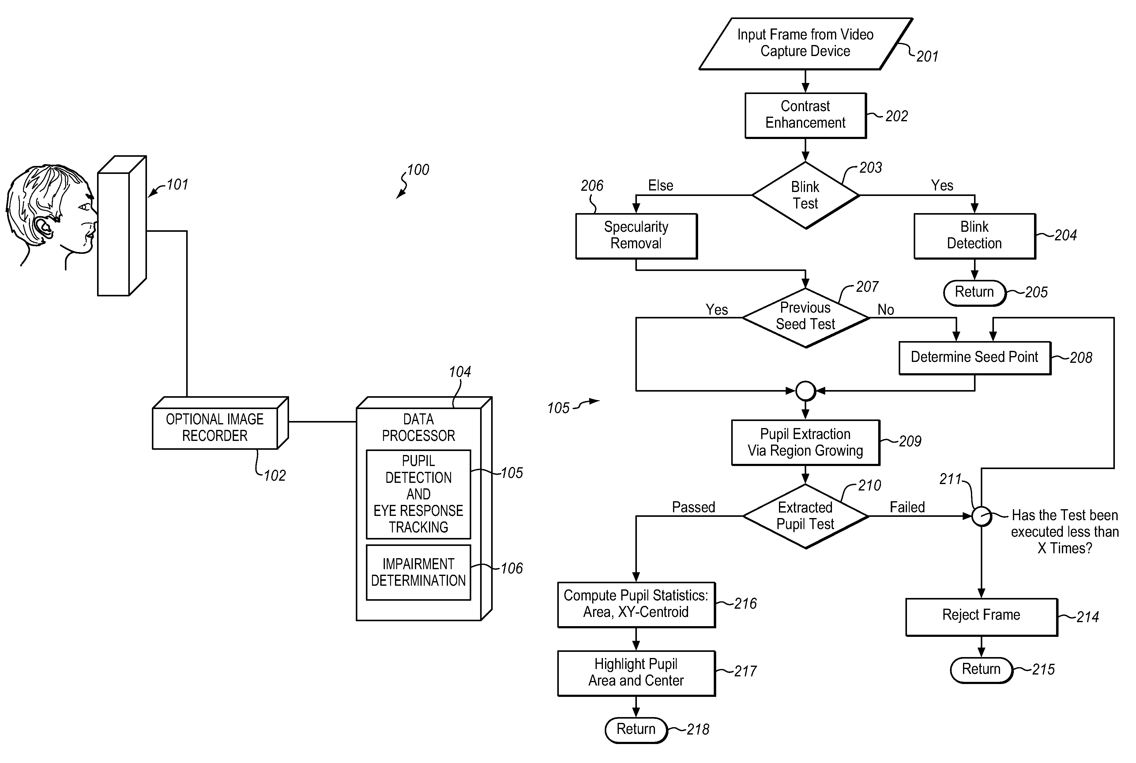
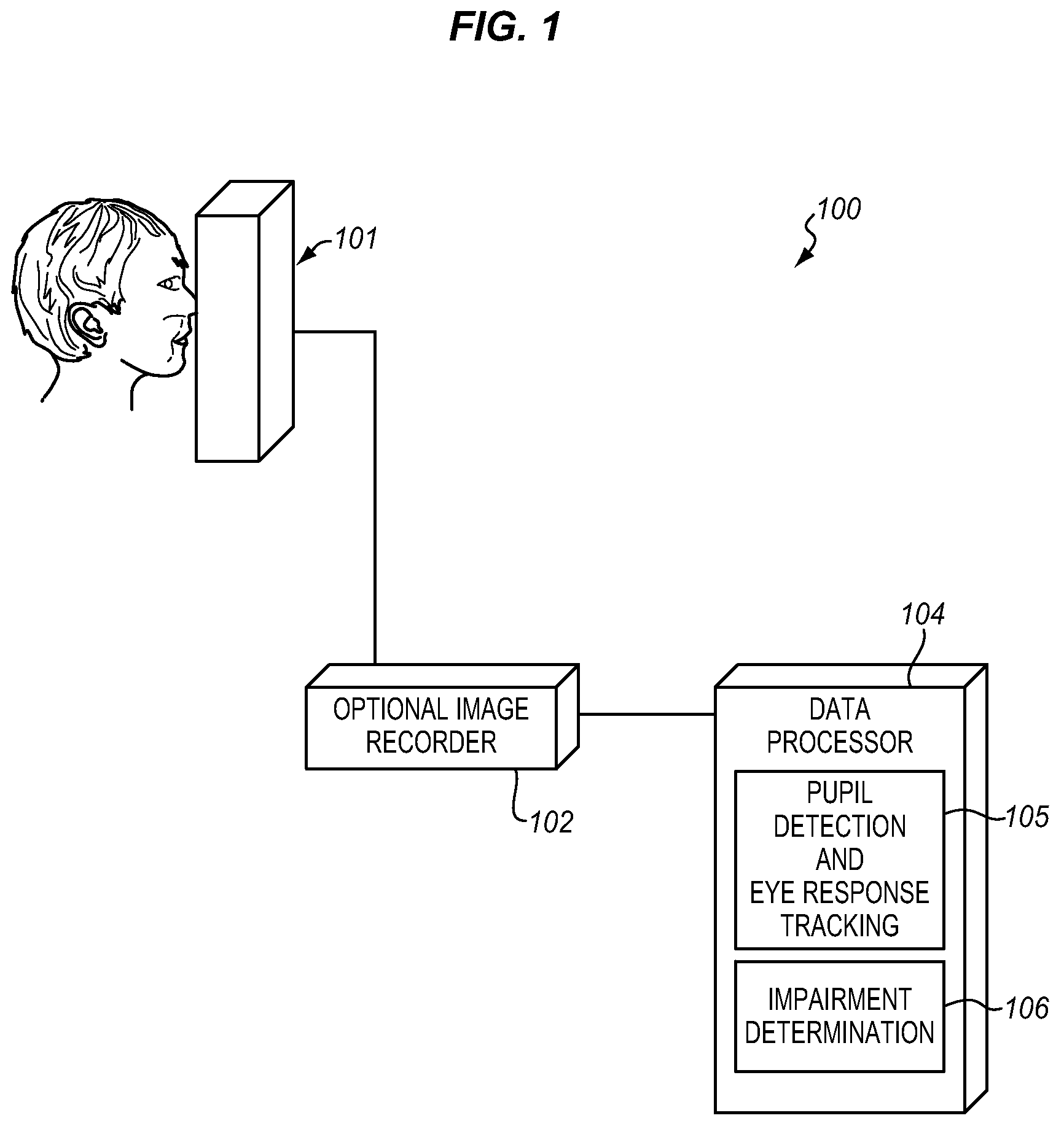
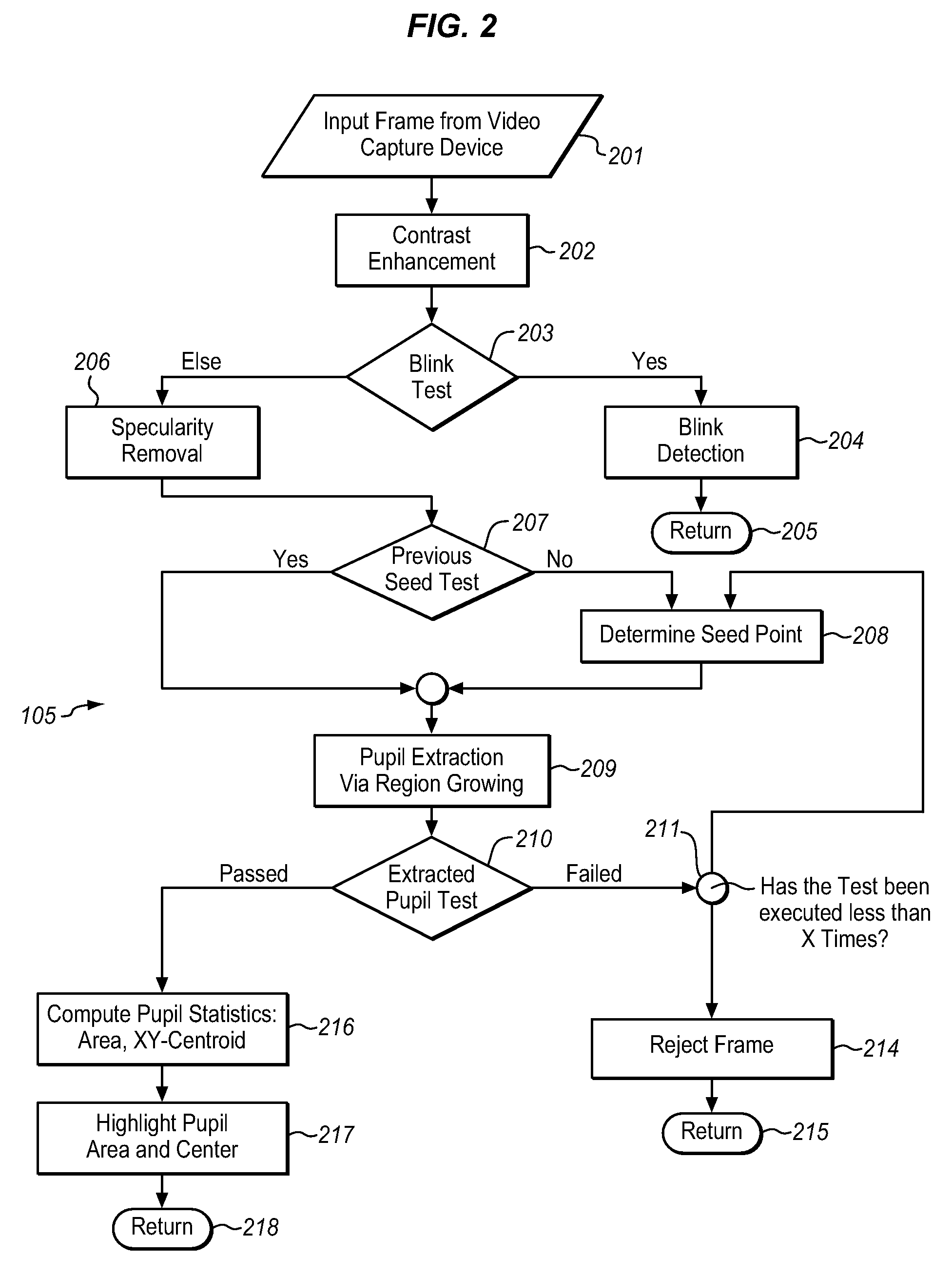
[0023]FIG. 1 illustrates a block diagram of the present pupil tracking system 105 which is implemented, for example, as part of an impairment determination system 100, where a user interface 101 is used to administer the predetermined test protocol to the subject. The use of the impairment determination system illustrates the operation of the present pupil tracking system and provides a practical example of the benefits of this system, and is not intended to limit the scope of the appended claims. In this application, the user interface 101 can be a device, such as that shown in the above-mentioned U.S. Pat. No. 5,137,345, which includes illu...


PUM


Abstract

The present system for analyzing eye responses accurately and automatically tracks the size, location, and movement of a subject's pupil(s) in response to a predetermined test protocol. These eye responses include both ocularmotor and pupillary responses to illumination and target tracking for either eye or both eyes simultaneously. The series of digital image frames of a subject's eyes, taken during the execution of a predetermined stimulus protocol, are automatically processed to determine pupil location, size, and responsiveness to changes in illumination.

Description

FIELD OF THE INVENTION[0001]This invention relates to a system for non-invasively tracking the size, location, and movement of a subject's pupil.BACKGROUND OF THE INVENTION[0002]It is a problem to accurately and automatically track the size, location, and movement of a subject's pupil(s) in response to predetermined stimuli. These measurements have use in various applications, and one of particular interest is to determine whether a subject is impaired, regardless of whether this is due to a medical condition, or the use of alcohol or drugs, or whether the subject is suffering from sleep deprivation or any other condition which interferes with the subject's ability to perform their assigned tasks. This is particularly a problem in the workplace where an employee who is presently functioning at a level of alertness that is less than their norm can place themselves and others in danger of injury, especially when the impaired employee is operating machinery. In addition, an impaired em...

Claims


Application Information

Patent Timeline
Patent Type & Authority Patents(United States)
IPC IPC(8): A61B3/14
CPCA61B3/113A61B5/162G06K9/00604G08B21/06G06K9/00845A61B5/163G06V40/19G06V20/597
Inventor WALDORF, RONALDMAUCH, BARBARA
Owner VISIONETX
Learn More