Optical pickup apparatus

a pickup apparatus and optical technology, applied in the field of optical pickup apparatus, can solve the problems of deterioration in the error rate at the time of reading data, variation of tr signal, failure as a tracking error may be generated, etc., to reduce the quantity of reflected light due to the adjacent layer incident to a subsidiary optical detector, reduce the jitter of data signal, and improve the reliability of read data.

Inactive Publication Date: 2010-09-14
HITACHI MEDIA ELECTORONICS CO LTD
View PDF3 Cites 1 Cited by
  • Summary
  • Abstract
  • Description
  • Claims
  • Application Information

AI Technical Summary

Benefits of technology

[0011]An object of the present invention is therefore to provide mitigate crosstalk to a data signal and a tracking signal in a multilayer optical disc without increase in size of an optical pickup apparatus.
[0012]In order to address the problems explained above, a method for reducing influence of reflection from adjacent layers has been employed.
[0016]According to an aspect of the present invention, jitter of data signal can be reduced and reliability of read data can also be improved, because influence on the optical detector of the reflected light from the adjacent layer can be suppressed. When three light beams are used, quantity of reflected light due to the adjacent layer incident to a subsidiary optical detector can be reduced and variation of tracking error signal due to interference can also be reduced. Therefore, an optical spot is no longer deviated from a track on the occasion of writing and reading data to and from an optical disc.

Problems solved by technology

Variation in the RF signal intensity as a total quantity of optical beam 811 generates deterioration in jitter of the RF signal, resulting in deterioration in an error rate at the time of reading the data.
Moreover, interference between the optical beams 812 and 813 also causes variation of the TR signal.
Therefore, such a failure as a tracking error may be generated.
Similarly, when an adjacent layer 512 is located near the objective lens of the read object layer 511, the reflected light is also generated from the adjacent layer, resulting in a problem of interference.

Method used


Image

  • Optical pickup apparatus
  • Optical pickup apparatus
  • Optical pickup apparatus

Examples


first embodiment

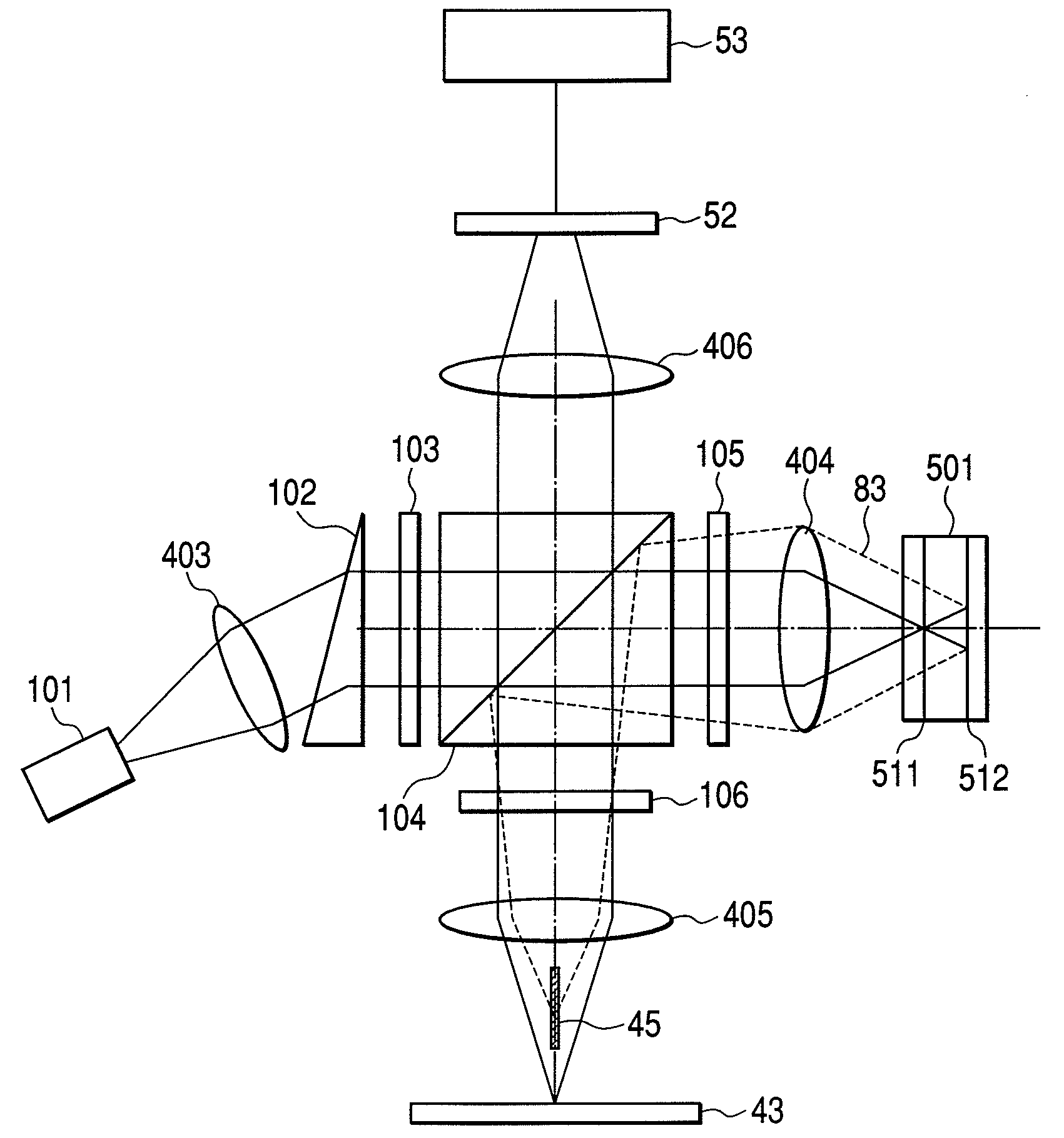
[0058]FIG. 1 shows an optical system of an optical pickup apparatus as a first embodiment of the present invention. A laser beam emitted from a semiconductor laser 101 is converted into a circularly collimated optical beam with a collimator lens 403 and a triangular prism 102. The collimated laser beam is split into three beams with a diffraction grating 103 formed of one main light beam and a couple of subsidiary light beams. Travelling direction of the main light beam is identical to the incident beam, but the subsidiary light beams become the emitted light beams having a certain inclination in both sides of the optical axis. Usually, difference in quantity of light beams between the main light beam and the subsidiary light beams is set to 10 times or more. Three laser beams are transmitted through a polarized beam splitter 104, converted to circular polarization with a λ / 4 plate 105, and are then focused with an objective lens 404 to a multilayer disc 501 being rotated with a rot...

second embodiment

[0064]FIG. 2 shows an optical system of the optical pickup apparatus as a second embodiment of the present invention. In this second embodiment, the diffraction grating 103 and the polarized beam splitter 104 are provided nearer the semiconductor laser 11 than the collimator lens 407. Therefore, the laser beam emitted from the semiconductor laser 101 is transmitted through the polarized beam splitter 104 under the state of divergent light beam, thereafter collimated with the collimator lens 407, and is then incident to the λ / 4 plate 105. In the first embodiment, since both diffraction grating 103 and the polarized beam splitter 104 have been provided at the area between the collimator lens 403 and the objective lens 404, the focusing lens 405 has also been required. However, in the second embodiment, since an optical beam reflected from the read object layer 511 of the multilayer disc 501 is converted to the convergent light beam as shown in FIG. 2, the focusing lens is no longer re...

third embodiment

[0065]FIG. 22 shows an optical system of the optical pickup apparatus as a third embodiment of the present invention. The reflected light from the optical disc 501 is reflected with the polarized beam splitter 104, thereafter converted into the circularly polarized light beam passing through the λ / 4 plate 106, and are then reflected by the reflection plate 43. The reflected light from the adjacent layer 512 is removed by the attenuation element 46. The reflection plate 43 is provided with the optical detector 52 at the area far from the optical axis, but this detector 52 does not detect in direct the reflected light from the optical disc reflected by the polarized beam splitter 104. Since the reflected light from the relevant layer 411 reflected by the reflection plate 43 passes through the λ / 4 plate 106 to become the light beam rotated by 90 degrees in its polarizing direction from the light beam entering the λ / 4 plate 106. Accordingly, this polarized light beam passes through the ...


PUM

PropertyMeasurementUnit
wavelengthaaaaaaaaaa
opticalaaaaaaaaaa
optical axisaaaaaaaaaa

Abstract

An optical pickup apparatus aiming at reduction of adverse effect on a tracking control signal and a data signal by preventing the reflected light from the adjacent layers of a multilayer disc changing to a stray light. In this optical pickup apparatus, the reflected light from the optical disc including the stray light from the adjacent layer is once focused with a focusing lens and is then reflected with the reflection plate. A flat attenuation element is provided between the lens and the reflection plate parallel to the optical axis with inclusion of the optical axis under the condition separated from the reflection plate. The reflection plate reflects the reflected light from the relevant layer and the attenuation element shields the reflected light from the adjacent layer. The light returning to the focusing lens includes less influence of the stray light. This light is detected with a detector to become a control signal and a data signal.

Description

CLAIM OF PRIORITY[0001]The present application claims priority from Japanese application JP 2007-181983 filed on Jul. 11, 2007, the content of which is hereby incorporated by reference into this application.FIELD OF THE INVENTION[0002]The present invention relates to an optical pickup apparatus and particularly to a read optical system of an optical pickup apparatus.BACKGROUND OF THE INVENTION[0003]Recording capacity of a single layer of an optical disc depends to a large extent on wavelength of a semiconductor laser used and a number of apertures (NA) of an objective lens. The shorter the wavelength of semiconductor laser is or the larger the number of apertures (NA) is, the larger recording density can be made and thereby the more capacity of a single layer can be increased. As the principal optical disc drive, a DVD (Digital Versatile Disc) drive using the red-color light in the wavelength near 650 nm and an objective lens having NA of 0.6 is available in the present market. Howe...

Claims


Application Information

Patent Timeline
Patent Type & Authority Patents(United States)
IPC IPC(8): G11B7/00
CPCG11B7/1362G11B7/1381G11B2007/0013
Inventor KIMURA, SHIGEHARUSHIMANO, TAKESHI
Owner HITACHI MEDIA ELECTORONICS CO LTD
Why Eureka
Try Eureka