
Reduction of dead-time distortion in class D amplifiers

a class d, dead-time distortion technology, applied in amplifiers, amplifiers with semiconductor devices only, amplifiers, etc., can solve the problems of distortion caused in this conventional arrangement, and distortion of sinusoid from intended signal, etc., to achieve the effect of reducing harmonic distortion

Active Publication Date: 2010-09-14
TEXAS INSTR INC
View PDF2 Cites 17 Cited by
  • Summary
  • Abstract
  • Description
  • Claims
  • Application Information

AI Technical Summary

Benefits of technology

The solution reduces harmonic distortion across various signal levels, enhances output fidelity, and is robust to manufacturing variations without increasing circuit complexity, thus improving the overall performance of class D amplifiers.

Problems solved by technology

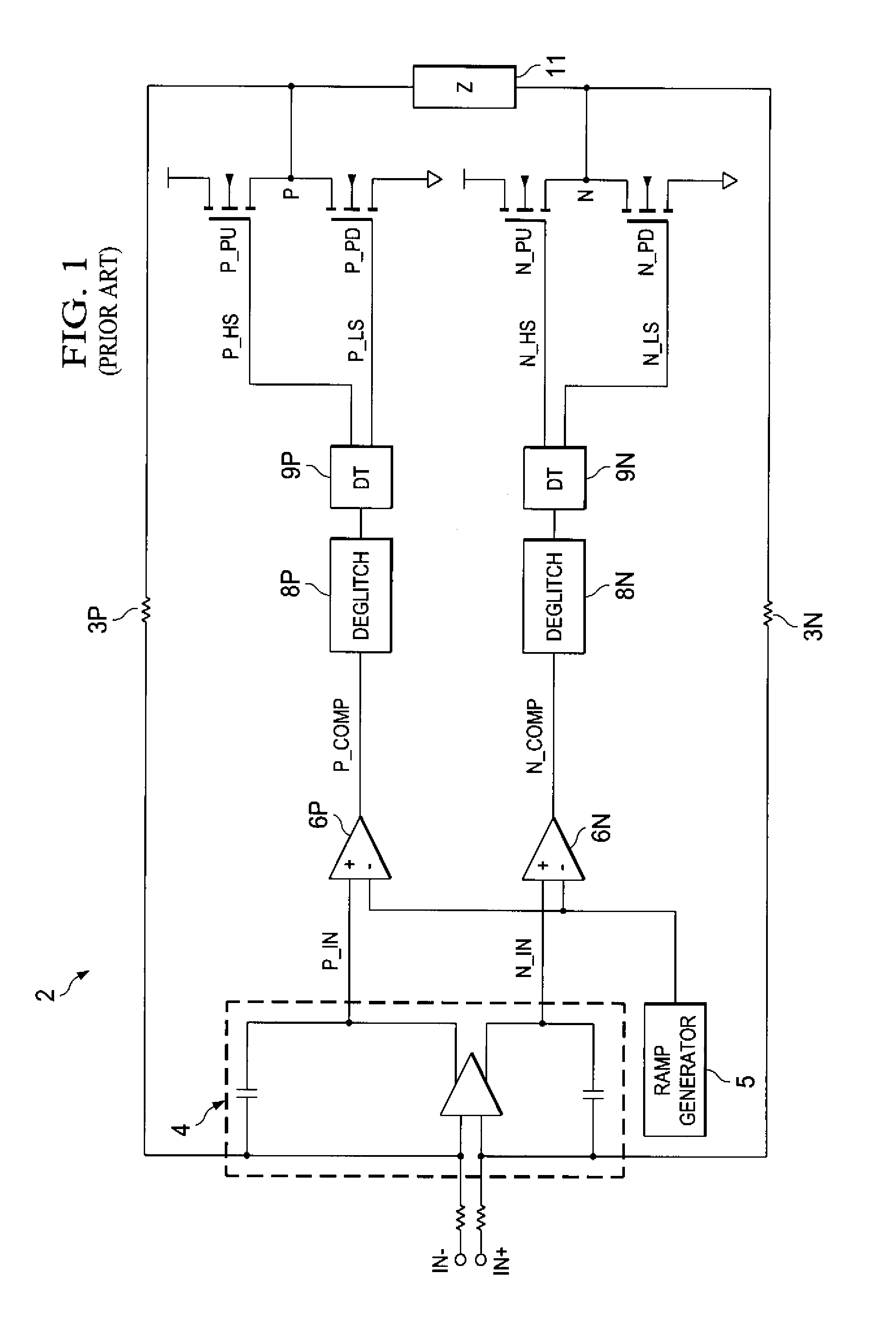
During the dead time, both of the pull-up and pull-down devices P_PU and P_PD are held off to ensure that both are not turned on at the same time, which would result in inefficient and potentially damaging rail-to-rail crowbar current through the output stage.
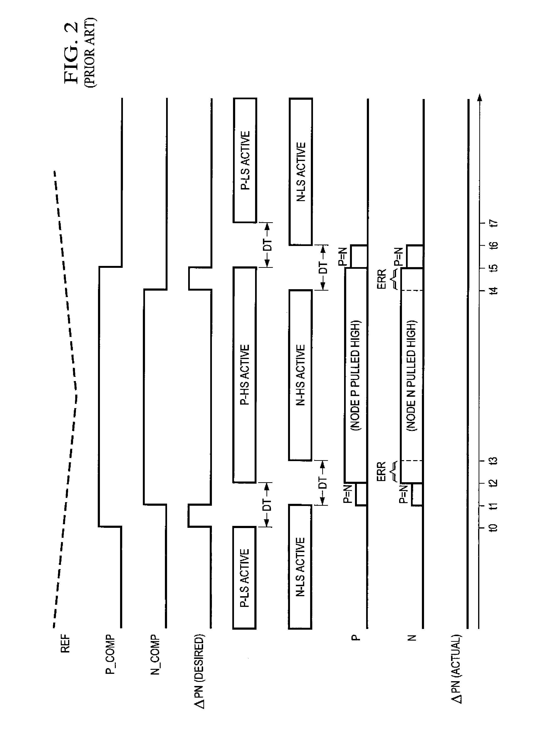
It has been observed, however, that distortion is caused in this conventional arrangement as a result of the “dead time” enforced by drive circuits 9P, 9N.
However, the dead-times DT in the operation of the practical circuit of FIG. 2 prevent this differential voltage from appearing across load 11.
In the case of an audio signal, this flattening of the sinusoid from the intended signal amounts to distortion.
However, a shorter dead-time increases the possibility of damaging “crowbar” current being conducted through the push-pull output drivers.
Such short dead-times are especially risky especially if the circuit is being manufactured in high quantities, considering the effects of process variations.

Method used


Image

  • Reduction of dead-time distortion in class D amplifiers
  • Reduction of dead-time distortion in class D amplifiers
  • Reduction of dead-time distortion in class D amplifiers

Examples


Embodiment Construction

[0038]The present invention will be described in connection with certain embodiments, namely as implemented into a digital audio amplifier. However, it is contemplated that this invention can also provide important benefits if applied in connection with other circuit and system applications for class D amplifiers. Accordingly, it is to be understood that the following description is provided by way of example only, and is not intended to limit the true scope of this invention as claimed.

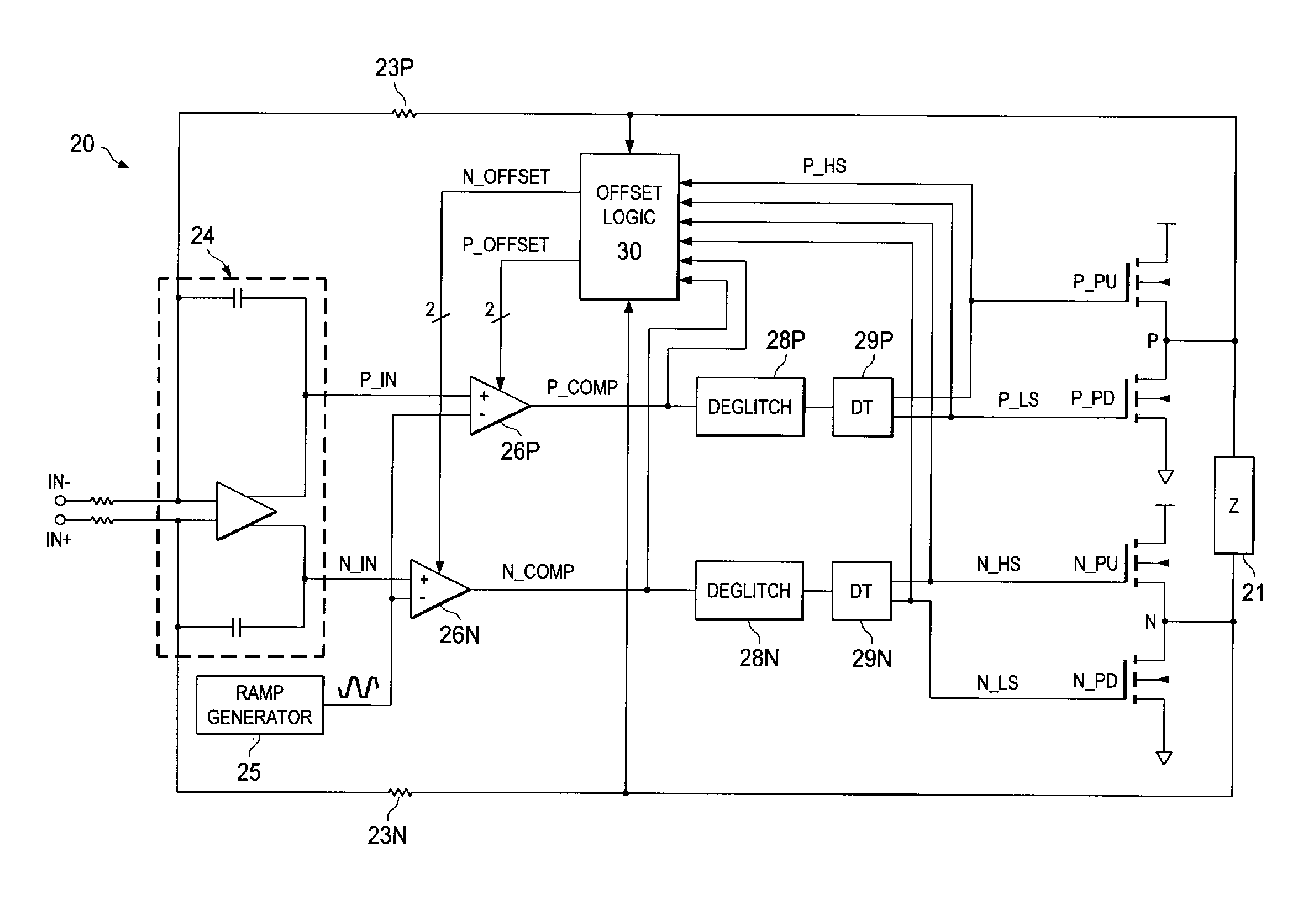
[0039]Referring now to FIG. 4, the construction of an example of amplifier 20 according to embodiments of the invention will now be described. Amplifier 20 in this example corresponds to a digital audio amplifier driving a loudspeaker or other device producing audible output. It is contemplated that amplifier 20 of FIG. 4 will typically be implemented as the output stage for a channel of a larger-scale digital audio system, such as a digital audio or audio / visual receiver, audio output circuitry for ...


PUM


Abstract

Pulse-width-modulating class D amplifier with an H-bridge output stage, and method of operating the same. in which output stage dead-time is compensated. Offset logic circuitry detects various dead-time-related conditions at push-pull output drivers, and generates an offset signal applied to the amplified differential input signal, to adjust the time at which the voltage at differential signal lines crosses a ramp reference waveform. The offset signal can correspond to the duration of a disturbance (dead-time at one driver in combination with an active signal at the active driver), or the sum of that disturbance duration with a dead-time at the active driver. The offset signal is generated by charging a capacitor for the duration of this disturbance, or disturbance plus dead-time. According to another approach, error is reduced by charging a capacitor for each transition of the signal for a duration of the dead-time of the active driver. Total harmonic distortion is reduced without requiring increased circuit complexity and without shortening the dead-time to unsafe margins.

Description

CROSS-REFERENCE TO RELATED APPLICATIONS[0001]Not applicable.STATEMENT REGARDING FEDERALLY SPONSORED RESEARCH OR DEVELOPMENT[0002]Not applicable.BACKGROUND OF THE INVENTION[0003]This invention is in the field of audio amplifiers, and is more specifically directed to reduction of harmonic distortion in class D audio amplifiers.[0004]Class D output amplifiers are now commonplace in modern digital audio systems, as well as in other systems that drive output loads with signals generated from digital signal processing. As known in the art, class D output amplifiers include half-bridge and full-bridge push-pull output stages that are driven digitally, for example by way of pulse-width modulation (PWM). At sufficiently high PWM frequencies, class D amplifiers can drive output loads, such as audio speakers, at precision and fidelity equal to conventional analog output stages, and at high output power levels.[0005]In the audio field, as well as in other applications, a common measure of outpu...

Claims


Application Information

Patent Timeline
Patent Type & Authority Patents(United States)
IPC IPC(8): H03F3/217
CPCH03F3/217
Inventor KAYA, CETINSHOOK, ADAM
Owner TEXAS INSTR INC
Learn More