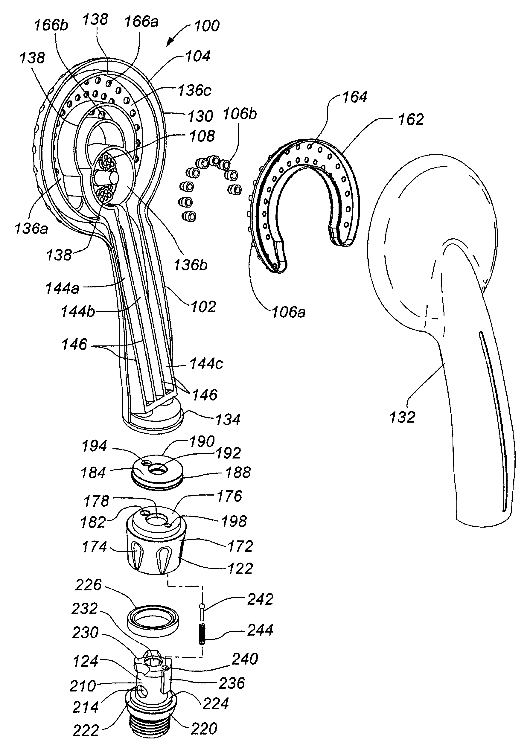
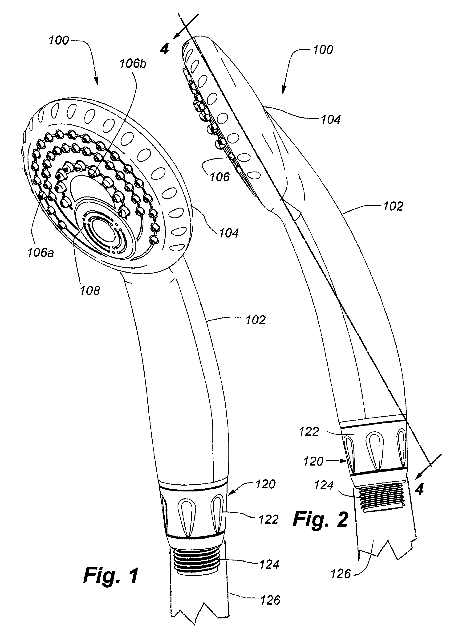
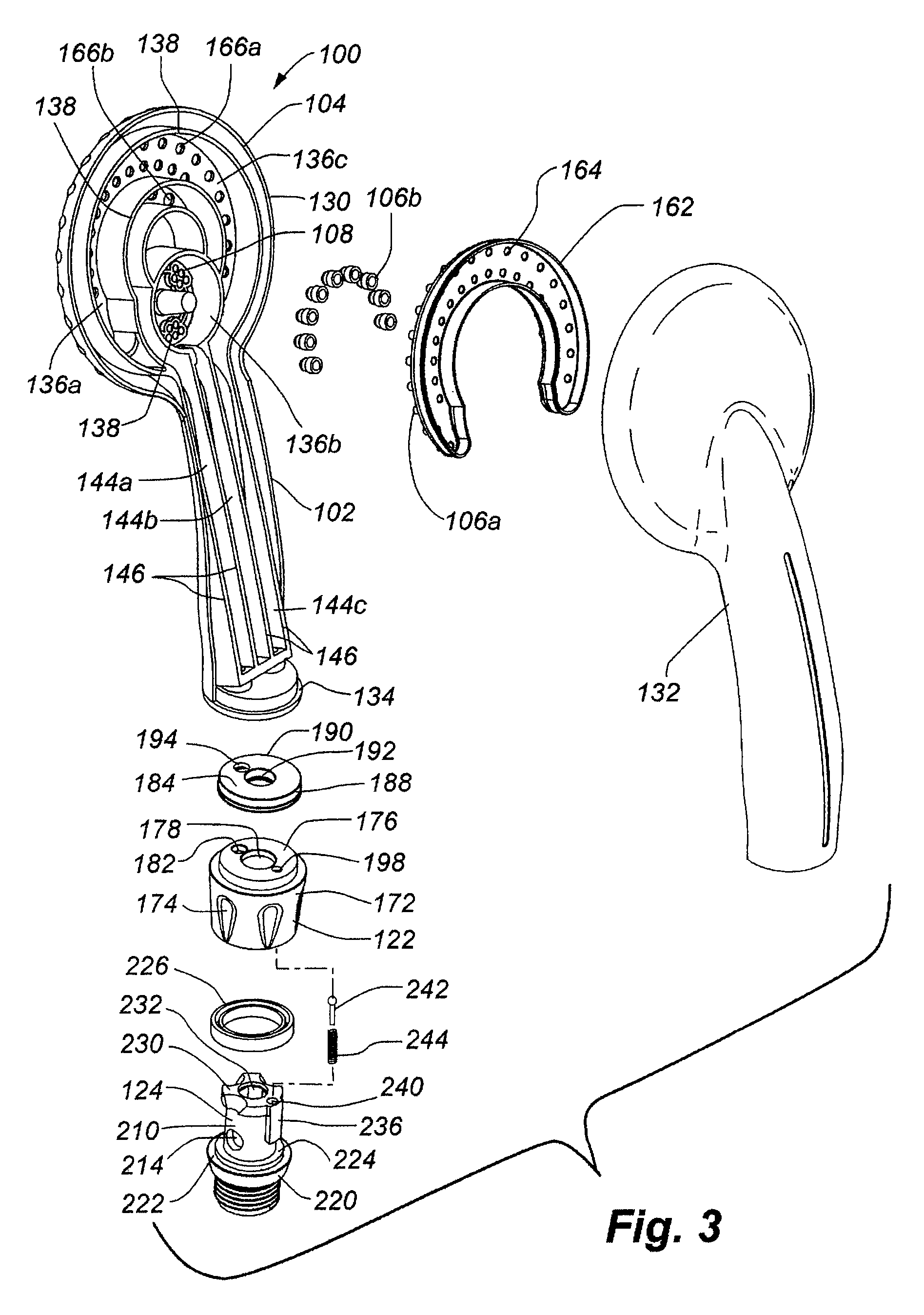
Handheld showerhead with mode control and method of selecting a handheld showerhead mode
a handheld shower and mode control technology, applied in the field of handheld showerheads, can solve the problems of limiting the options of designing an aesthetically pleasing showerhead and directing the shower flow potentially in multiple directions, and not being able to meet the needs of showering
- Summary
- Abstract
- Description
- Claims
- Application Information
AI Technical Summary
Benefits of technology
Problems solved by technology
Method used
Image
Examples
first embodiment
[0085]With reference to FIGS. 11-16, the showerhead portion 302 may include a front showerhead portion 310 and a rear showerhead portion 312. Similar to the first embodiment, the front showerhead portion 310 may include three front showerhead fluid chambers 314 defined by front showerhead sidewalls 316 and in fluid communication with one set of nozzles 318a-c, and the rear showerhead portion 312 may include three rear showerhead fluid chambers 320 defined by rear showerhead sidewalls 322. Together the front and rear showerhead fluid chambers 314, 320 may define showerhead fluid chambers in fluid communication with sets of showerhead nozzles 318. Together front and rear fluid channels 324, 326 defined within each showerhead portion 310, 312 provide fluid communication between the showerhead fluid chambers and base fluid apertures 330 defined by a showerhead base 332 as shown in FIGS. 13, 14 and 17.
[0086]As described above, the front and rear showerhead sidewalls 316, 322 may be heat ...
third embodiment
[0100]With reference to FIGS. 21 and 22, the third embodiment may include four sets of nozzles 404 and / or openings 408 for delivering fluid from the showerhead portion 402 in up to four spray modes. Each set of nozzles 404 and / or openings 406 may fluidly communicate with a one or more distinct showerhead fluid chambers defined within the showerhead portion 402 like the other embodiments. Turning to FIG. 23, each showerhead fluid chamber, in turn, may be in fluid communication with a fluid channel 412a-d defined by fluid channel sidewalls 414. As with other embodiments, more than fluid channel 412 may fluidly communicate with a showerhead fluid chamber.
[0101]With reference to FIGS. 23-26, each fluid channel 412a-d may extend from the showerhead portion 402 to the water supply connector 416 for the showerhead. The fluid channels 412a-d terminate proximate a valve core 418. As described in more detail below, rotation of the valve core 418 relative to the water supply connector 416 sele...
fourth embodiment
[0116]Although the fourth embodiment operates in a similar manner to the previously described embodiments, individual components may be slightly modified. For example, the handle portion and the mode selector 502 may be a single component. As another example, the mode selector 502 slides along the longitudinal axis of the water supply connector 504.
[0117]The showerhead portion for the fourth embodiment is omitted. However any showerhead portion, including any described above, having fluid channels (which may be formed within the showerhead portion, or by using elements, such as hoses, tubes or the like, or by some combination thereof) arranged to fluidly communicate with the fluid channels defined in an upper portion of the water supply connector 504 may be used for the showerhead portion.
[0118]Turning to FIGS. 30-37, the water supply connector 504 may include a generally cylindrical water supply connector shaft 506 separated into upper and lower water supply connector portions 508,...
PUM
 Abstract
Description
Claims
Application Information
 - R&D
- Intellectual Property
- Life Sciences
- Materials
- Tech Scout
- Unparalleled Data Quality
- Higher Quality Content
- 60% Fewer Hallucinations
Browse by: Latest US Patents, China's latest patents, Technical Efficacy Thesaurus, Application Domain, Technology Topic, Popular Technical Reports.
© 2025 PatSnap. All rights reserved.Legal|Privacy policy|Modern Slavery Act Transparency Statement|Sitemap|About US| Contact US: help@patsnap.com


