
Engine braking apparatus with mechanical linkage and lash adjustment

a technology of braking apparatus and lash adjustment, which is applied in the direction of mechanical apparatus, machines/engines, output power, etc., can solve the problems of obviating the danger of accidents resulting from brake failure, overheating and failure of brakes, and using wheel brakes

Active Publication Date: 2010-09-07
JACOBS VEHICLE SYST
View PDF25 Cites 27 Cited by
  • Summary
  • Abstract
  • Description
  • Claims
  • Application Information

AI Technical Summary

Benefits of technology

The solution provides a cost-effective, reliable, and efficient engine braking system that can be installed on various engines, including smaller ones, without requiring redesign of engine components, and operates effectively across all engine speeds, reducing the load on engine components and minimizing noise.

Problems solved by technology

While the normal drum or disc type wheel brakes of the vehicle are capable of absorbing a large amount of energy over a short period of time, their repeated use, for example, when operating in hilly terrain, could cause brake overheating and failure.
The use of an engine brake will substantially reduce the use of the wheel brakes, minimize their wear, and obviate the danger of accidents resulting from brake failure.
However, the prior art engine braking systems have certain inherent disadvantages that have limited their application to primarily larger vehicles such as heavy duty trucks (and typically, on engines having a displacement of about 10 liters or more), and their retrofit to existing engines is largely impossible without substantial modification of the engine cylinder head.
One of the disadvantages associated with the conventional prior art CREB system is due to the fact that the load from engine braking is supported by the engine components.
Thus, the overall weight, height, and cost of using the prior art CREB system are likely to be excessive, and limit its commercial application.
Another disadvantage associated with the conventional prior art CREB system is the high and unique noise generated by the releasing of high-pressure gas or “blow down” through the exhaust valve(s) during the compression stroke, near the top dead center position of the engine piston.
Additional disadvantages of the prior art systems reside in their relative complexity and the necessity for using precision components because they require accurate timing and hydraulic actuators capable of opening the exhaust valves precisely when required.
Thus they may be comparatively expensive and difficult or impossible to install on certain engines.
Yet another disadvantage associated with the conventional prior art CREB system of hydraulic type is the compliance of the braking system, which may cause the braking valve lift to collapse at the peak braking load (near compression top dead center (TDC) of the engine piston) and further increase the braking load.
The large reduction of braking valve lift due to compliance will reduce the braking performance and excessive braking load may cause engine damage.
These parts and features all add cost and complexity, and reduce system reliability.
Finally, such type of engine brakes cannot be retrofitted into existing engines.
Moreover, the introduction of the extra exhaust valve creates an extra pocket in the combustion chamber, which increases engine emission.
Also, such type of engine brakes can not be used in existing engines.
The BTEB system of the type described above may not be reliable because it depends on the intermediate opening or floating of the braking exhaust valve, which is not consistent, both in timing and magnitude.
As is well known in the art, exhaust valve floating is highly engine speed dependent and affected by the quality and control of the exhaust brake, and also the design of the exhaust manifold.
There may be not enough or none valve floating for the actuation of the engine braking device at middle and low engine speeds when the engine brake is highly demanded since the engine is mostly driving at such speeds.
Again, such type of engine brakes may not be able to retrofit into existing engines.
The BTEB system of the type described above is dedicated to a particular type of engine that has high-pressure oil rail (source), which greatly limits its application.
Also, such type of engine brakes cannot be retrofitted into existing engines.
(a) The system can only be installed on a particular type of engines;
(b) The system cannot be retrofitted to existing engines;
(c) The engine braking load is carried by the engine components;
(d) The system installment needs redesign of the engine or engine components;
(e) The system has too many components and is too complex;
(f) The system increases the manufacturing tolerance requirements and is too costly;
(g) The system is not reliable and only work at certain engine speeds; and

Method used


Image

  • Engine braking apparatus with mechanical linkage and lash adjustment
  • Engine braking apparatus with mechanical linkage and lash adjustment
  • Engine braking apparatus with mechanical linkage and lash adjustment

Examples


Embodiment Construction

[0069]Reference will now be made in detail to presently preferred embodiments of the invention, examples of which are illustrated in the accompanying drawings. Each example is provided by way of explanation, not limitation, of the invention. In fact, it will be apparent to those skilled in the art that modifications and variations can be made in the present invention without departing from the scope and spirit thereof. For instance, features illustrated or described as part of one embodiment may be used on another embodiment to yield a still further embodiment. Thus, it is intended that the present invention covers such modifications and variations as come within the scope of the appended claims and their equivalents.

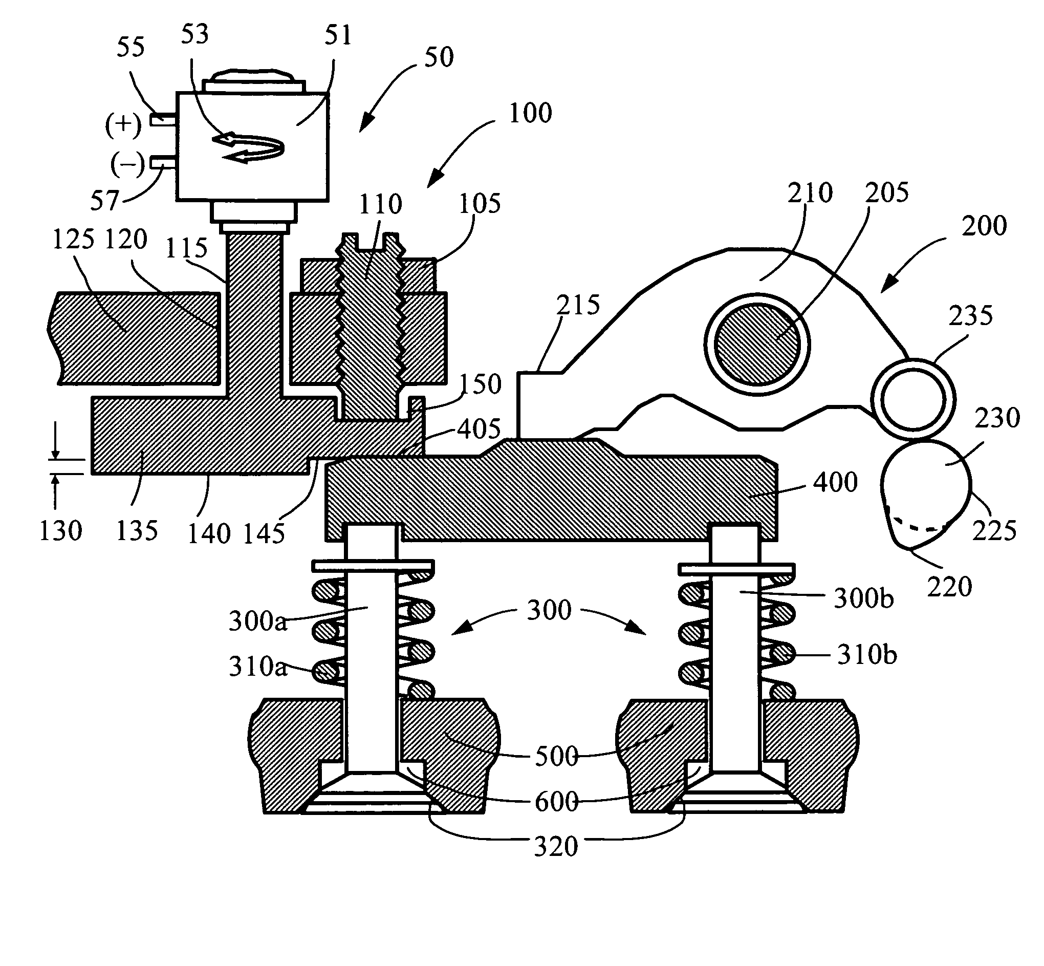
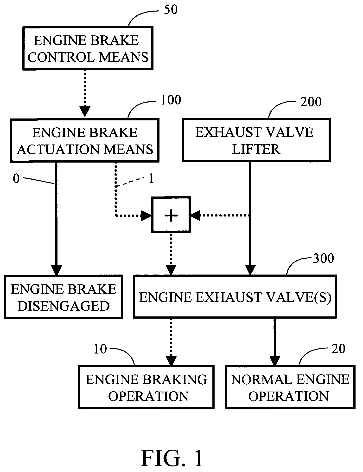
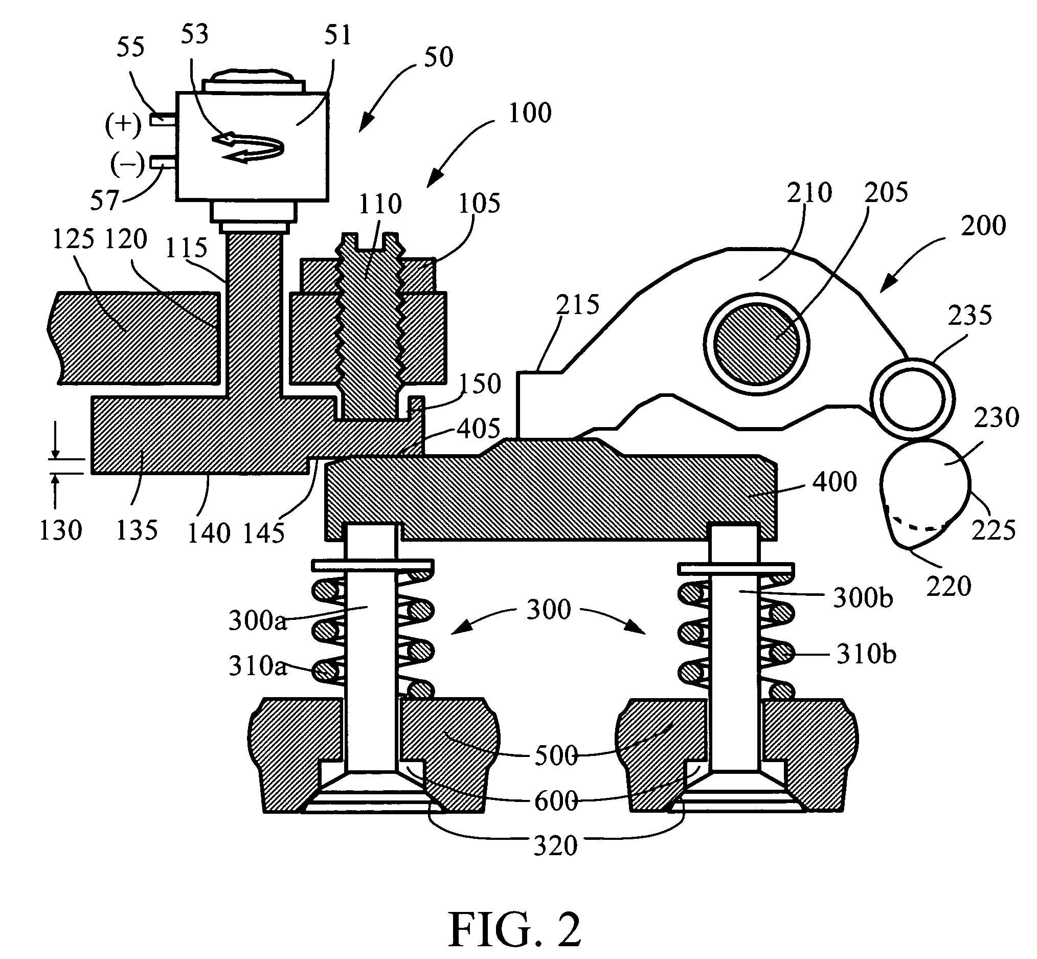
[0070]FIG. 1 is a flow chart illustrating the general relationship between a normal engine operation 20 and an added engine braking operation 10 according to one version of the present invention. An internal combustion engine contains at least one exhaust valve 300 and ...


PUM


Abstract

An apparatus for modifying engine valve lift to produce an engine valve event in an internal combustion engine comprises actuation device for operating at least one exhaust valve, and control device for moving the actuation device between its inoperative position and operative position. In the inoperative position, the actuation device is disengaged from the at least one exhaust valve, and in the operative position, the actuation device holds open the at least one exhaust valve to produce the modified engine valve lift for the engine valve event, which includes an engine braking event. The actuation device includes a motion limiting apparatus for controlling movement of the actuation device. The actuation device can be integrated into a valve bridge and other valve train components, such as a rocker arm, wherein a plunger is slidably disposed between the inoperative position and the operative position.

Description

BACKGROUND OF THE INVENTION[0001]1. Field of Invention[0002]The present invention relates generally to the modification of engine valve lift for producing an engine valve event in an internal combustion engine, particularly to engine braking apparatus and methods for converting an internal combustion engine from a normal engine operation to an engine braking operation.[0003]2. Prior Art[0004]It is well known in the art to employ an internal combustion engine as brake means by, in effect, converting the engine temporarily into a compressor. It is also well known that such conversion may be carried out by cutting off the fuel and opening the exhaust valve(s) at or near the end of the compression stroke of the engine piston. By allowing compressed gas (typically, air) to be released, energy absorbed by the engine to compress the gas during the compression stroke is not returned to the engine piston during the subsequent expansion or “power” stroke, but dissipated through the exhaust an...

Claims


Application Information

Patent Timeline
Patent Type & Authority Patents(United States)
IPC IPC(8): F02D13/04F02D13/08
CPCF01L1/181F01L13/06F01L1/26F01L2820/032F02D13/04F02M25/0752F02M26/01
Inventor YANG, ZHOU
Owner JACOBS VEHICLE SYST
Learn More