
Method and apparatus for identifying an imaging device

a technology of imaging device and identification method, which is applied in the field of method and apparatus, can solve the problems of significant limitations and/or limited reliability of all prior approaches to identifying the device that acquired a particular image, loss during image processing, and inability to observe pixel defects in every scene, etc., and achieve the effect of reliable identification of the devi

Inactive Publication Date: 2010-08-31
THE RES FOUND OF STATE UNIV OF NEW YORK
View PDF1 Cites 14 Cited by
  • Summary
  • Abstract
  • Description
  • Claims
  • Application Information

AI Technical Summary

Benefits of technology

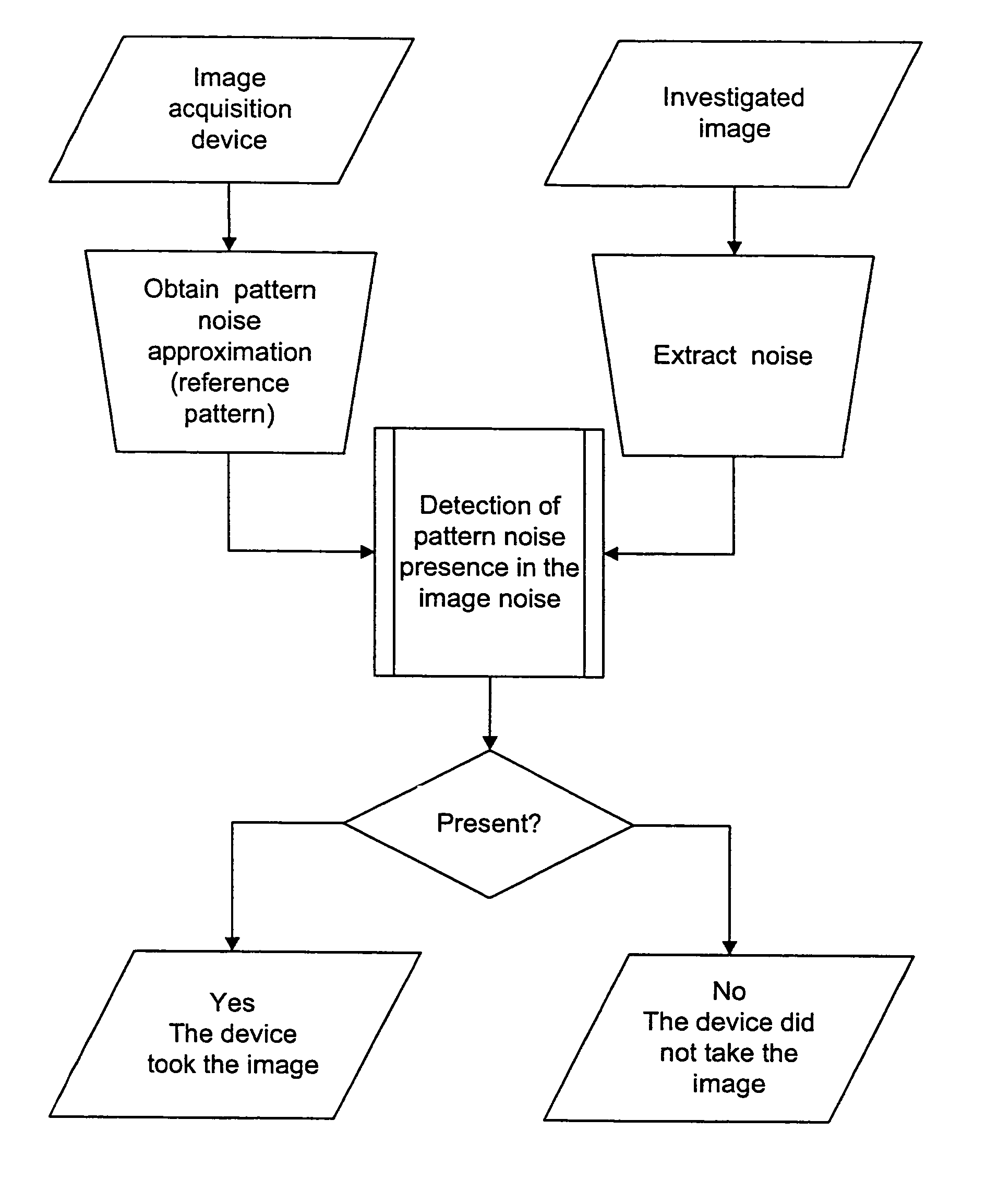
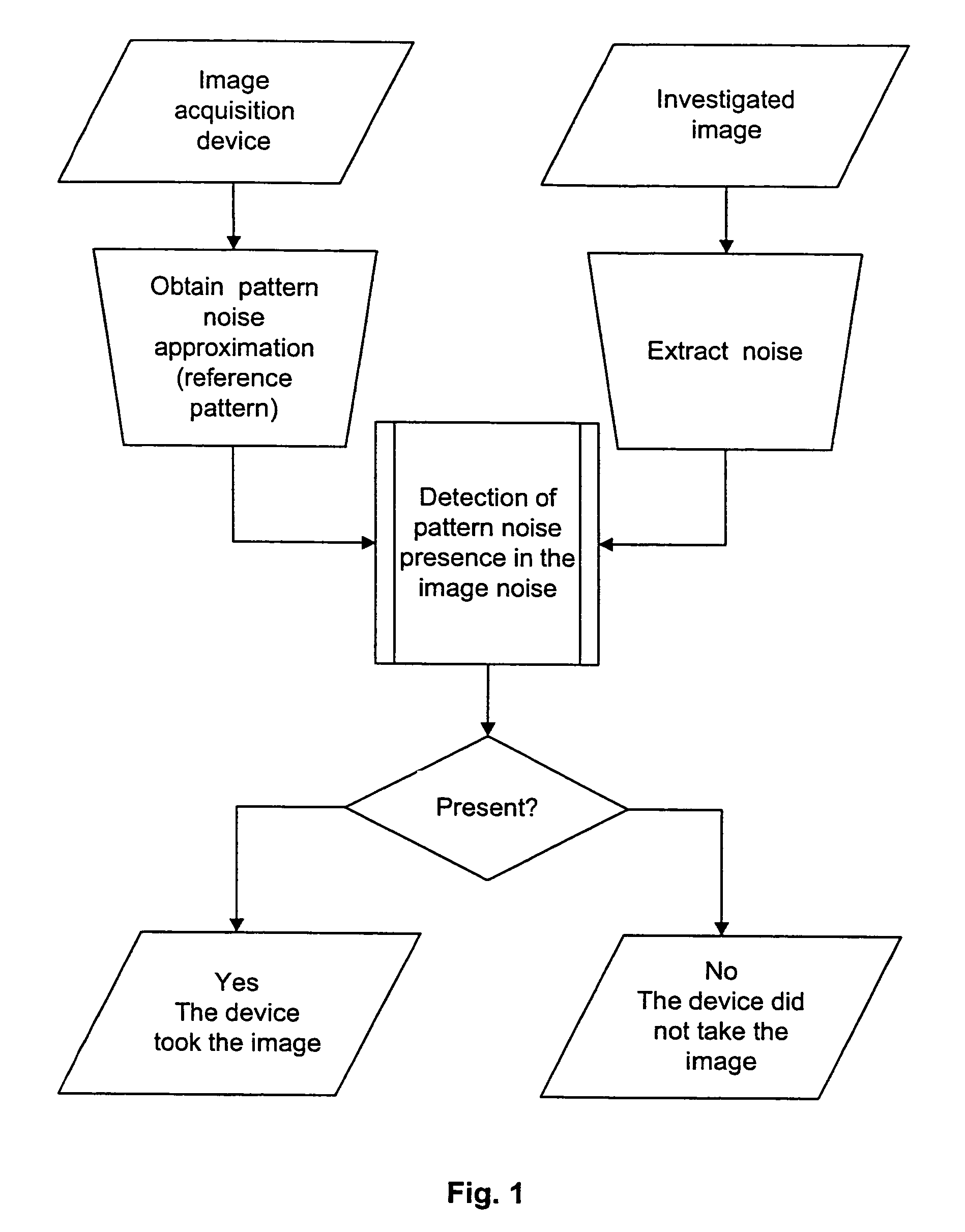
The present invention provides a way to identify the device that took a picture or video, even from processed images. It does this by using the unique pattern of noise that is present in every digital imaging sensor. This technique can be used to distinguish between different cameras or sensors, even if they are from the same make and model. The method involves determining the reference pattern noise of the sensor, searching the image for the reference pattern, and identifying if it is present or not. This information can be used to verify the identity of the sensor and the image it captured.

Problems solved by technology

A practical and important problem in digital forensics today is to identify reliably the imaging device that acquired a particular electronic image or representation thereof.
All prior approaches to identifying the device that acquired a particular image have significant limitations and / or limited reliability.
However, this information can be easily modified by an attacker, or it may be lost during processing of the image.
Additionally, pixel defects might not be observable in every scene.
This approach is not likely to be applicable to scanners either.
This method is less practical, since it requires a large number of images for training the classifier.
Also, the reliability of this method may not rise to the standard required for legal evidence.
The fact that the dark current can only be extracted from dark frames severely limits practical applications of this method.
Moreover, because the dark current is a relatively weak signal, the reliability of camera identification based on dark current is limited.

Method used


Image

  • Method and apparatus for identifying an imaging device
  • Method and apparatus for identifying an imaging device
  • Method and apparatus for identifying an imaging device

Examples


Embodiment Construction

[0018]The completely new approach of the present invention to identify an individual acquisition device from an image makes use of a pattern noise from the imaging sensor (Holst, G. C., CCD Arrays, Cameras, and Displays, 2nd edition (JCD Publishing & SPIE Press, USA, 1998)). Slight imperfections in the manufacturing of the imaging sensor and inhomogeneities of silicon wafers cause the pattern noise, which is present in all types of imaging sensors (CCD, CMOS, JFET) currently in use. This pattern noise is automatically and necessarily superimposed on each image the sensor acquires, similar to the process by which a gun barrel imposes specific scratches on a bullet fired from it.

[0019]Referring to FIG. 1, the present invention shows whether or not a particular device acquired a given image. An approximation to its pattern noise (the device's reference pattern noise) is obtained for each suspected device. Ways to do that are presented below at paragraphs [033]-[036]. To detect a simila...


PUM


Abstract

A new technique for identifying from images a camera, or other imaging device such as a scanner, is based on the device's reference noise pattern, a unique stochastic characteristic of all common digital imaging sensors, including CCD, CMOS (Foveon™ X3), and JFET. First, one determines from images the sensor's reference pattern noise, which uniquely identifies each sensor. To identify the sensor from a given image, the presence or absence of the reference pattern noise in the image under examination is established using a correlation detector or other means.

Description

STATEMENT OF GOVERNMENT INTEREST[0001]This invention was made with Government support under Contract F30602-02-2-0093 awarded by the Air Force. The Government has certain rights in this invention.BACKGROUND OF THE INVENTION[0002]This invention pertains to identifying an electronic image sensor (e.g., a CCD or CMOS sensor) from an electronic image (i.e., deciding which digital camera or other image-capture device acquired a given electronic image).[0003]A practical and important problem in digital forensics today is to identify reliably the imaging device that acquired a particular electronic image or representation thereof. Techniques to authenticate an electronic image are especially important in court. For example, identifying the source device could establish the origin of images presented as evidence. In a prosecution for child pornography, for example, one could prove that certain imagery was obtained with a specific camera and is thus not an image generated by a computer. As e...

Claims


Application Information

Patent Timeline
Patent Type & Authority Patents(United States)
IPC IPC(8): H04N5/217
CPCG06V20/80G06V20/90
Inventor FRIDRICH, JESSICAGOLJAN, MIROSLAVLUKAS, JAN
Owner THE RES FOUND OF STATE UNIV OF NEW YORK
Learn More