Alignment method and apparatus of mask pattern

a mask pattern and alignment method technology, applied in the field of alignment methods and apparatus of mask patterns, can solve the problems of inability to form the second layer pattern with high pattern arrangement precision, deficient stability of the optical system of the exposure apparatus, and difficulty in performing exposure in a fully stable state, so as to improve the pattern arrangement accuracy

Inactive Publication Date: 2010-08-24
TDK CORPARATION
View PDF12 Cites 0 Cited by
  • Summary
  • Abstract
  • Description
  • Claims
  • Application Information

AI Technical Summary

Benefits of technology

[0008]It is therefore an object of the present invention to provide an alignment method and apparatus of mask patterns whereby, when a second layer pattern is stacked over a first layer pattern, it is possible to improve accuracy in pattern-arrangement of the second layer while the alignment accuracy of the second layer relative to the first layer is maintained.
[0011]Accordingly, as in the present invention, during the pattern arrangement state A where accuracy of a coordinate system is maintained higher, that is, when forming the first layer, the alignment is performed by compensating offsets, a residual rotation error, the linear expansion and contraction of the wafer and the orthogonal error, and the alignment is performed when forming the second layer only by minimizing an offset between the center position of the first layer pattern and the center position of a second mask pattern and a residual rotation error between the wafer and the second mask pattern, the pattern arrangement accuracy of the second layer can be brought into the same level as of the pattern arrangement state A. Thus, the pattern arrangement accuracy of the second layer can be improved with the alignment accuracy of the second layer relative to the first layer maintained.
[0018]Accordingly, as in the present invention, during the pattern arrangement state A where accuracy of a coordinate system is maintained higher, that is, when forming the first layer, the alignment is performed by compensating offsets, a residual rotation error, the linear expansion and contraction of the wafer and the orthogonal error, and the alignment is performed when forming the second layer only by minimizing an offset between the center position of the first layer pattern and the center position of a second mask pattern and a residual rotation error between the wafer and the second mask pattern, the pattern arrangement accuracy of the second layer can be brought into the same level as of the pattern arrangement state A. Thus, the pattern arrangement accuracy of the second layer can be improved with the alignment accuracy of the second layer relative to the first layer maintained.

Problems solved by technology

However, according to the conventional alignment method, because the amount of deviation of the first layer was measured and then the alignment was compensated using the measured deviation of the first layer when forming the second layer pattern, it was impossible to form the second layer pattern with high pattern arrangement precision.
This is due to the fact that a state of an optical system in the exposure apparatus was deficient in stability when the second layer pattern was formed.
Particularly, when the optical system of the exposure apparatus was adjusted and the amount of deviation was compensated, it took a long time until the system was stabilized, so that it was quite difficult to perform exposure in a fully stable state.

Method used


Image

  • Alignment method and apparatus of mask pattern
  • Alignment method and apparatus of mask pattern
  • Alignment method and apparatus of mask pattern

Examples


Embodiment Construction

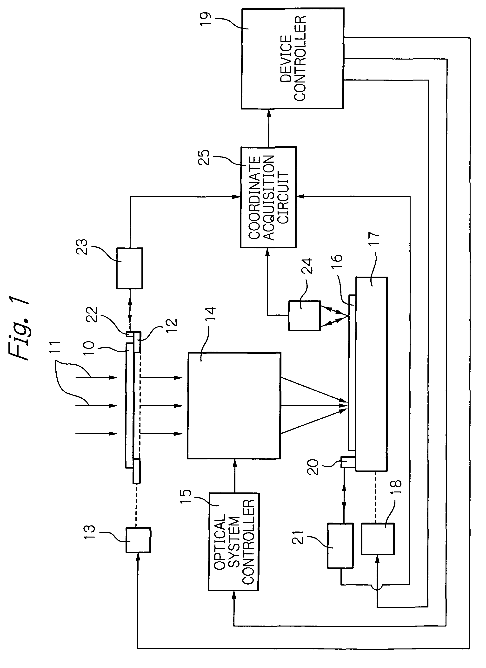
[0026]FIG. 1 schematically illustrates a basic configuration of a projection-type exposure apparatus in an embodiment according to the present invention.

[0027]In the figure, reference numeral 10 denotes a reticle having a mask pattern, through which irradiated exposure light 11 is passed, 12 denotes a reticle-holding stage for holding the reticle 10, 13 denotes a reticle-driving device for two-dimensionally moving and slightly rotating the reticle holding stage 12 in orthogonal coordinates (X, Y) directions within a plane perpendicular to an optical axis of the exposure light 11, 14 denotes an optical projection system for converging the exposure light passed through the reticle 10 onto a surface of a wafer, 15 denotes an optical system controller for adjusting magnification, aberration and the like of the optical projection system 14, 16 denotes a wafer, 17 denotes a wafer-holding stage for holding the wafer 16 on its surface, and 18 denotes a wafer-driving device for two-dimension...


PUM


Abstract

An alignment method of mask patterns includes forming a first layer by transferring a first mask pattern onto a wafer, forming a second layer by transferring a second mask pattern onto the first layer, and particularly a first alignment step, forming the first layer, which performs alignment for minimizing offset between a center position of the wafer and a center position of the first mask pattern and a residual rotation error between the wafer and the first mask pattern and additional alignment for compensating an amount of possible deviation of superposition of the second layer pattern on the first layer pattern, and a second alignment step, forming the second layer, which performs only alignment for minimizing offset between a center position of the first layer pattern and a center position of the second mask pattern and a residual rotation error between the first layer pattern and the second mask pattern.

Description

BACKGROUND OF THE INVENTION[0001]1. Field of the Invention[0002]The present invention relates to an alignment method and apparatus of mask patterns when the mask patterns are transferred onto a wafer using an exposure apparatus.[0003]2. Description of the Related Art[0004]A photolithography process performed when manufacturing a thin-film device such as a thin-film magnetic head, a micro device, a semiconductor device, a liquid crystal display device and the like includes a step of transferring a mask pattern onto a wafer using an exposure apparatus such as, for example, a step of projecting and transferring a mask-pattern image onto each shot area by using a stepper. In such mask-pattern transferring step, it is required to accurately carry out alignment between a pattern on the mask called a reticle and a shot area on the wafer.[0005]Hereinafter, described will be a conventional alignment method in case that patterns of a plurality of layers are stacked with each other, that is, f...

Claims


Application Information

Patent Timeline
Patent Type & Authority Patents(United States)
IPC IPC(8): G03B27/68G03B27/42
CPCG03F7/70616G03F7/70633G03F7/70783G03F7/7085G03F9/7003
Inventor KAMIJIMA, AKIFUMIYATSU, HIDEYUKIHATATE, HITOSHI
Owner TDK CORPARATION
Why Eureka
Try Eureka