
Housing for a seismic sensing element, and a seismic sensor

a seismic sensing element and housing technology, applied in seismology, seismology for water-covered areas, mechanical vibration separation, etc., can solve the problems of poor seismic coupling, inability to meet, and inconsistent fidelity between the measured horizontal and vertical components of seismic data, so as to achieve good seismic coupling, accurate recording, and good seismic coupling

Active Publication Date: 2010-08-17
REFLECTION MARINE NORGE AS
View PDF26 Cites 23 Cited by
  • Summary
  • Abstract
  • Description
  • Claims
  • Application Information

AI Technical Summary

Benefits of technology

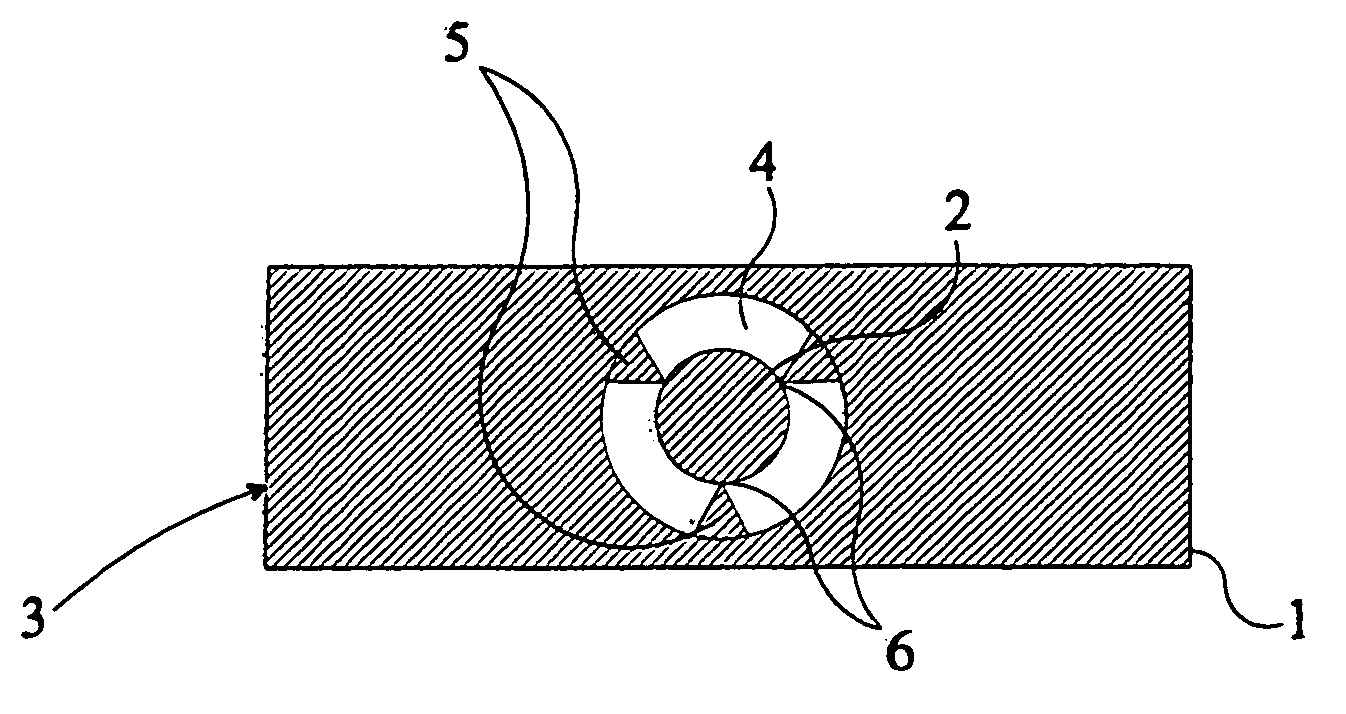
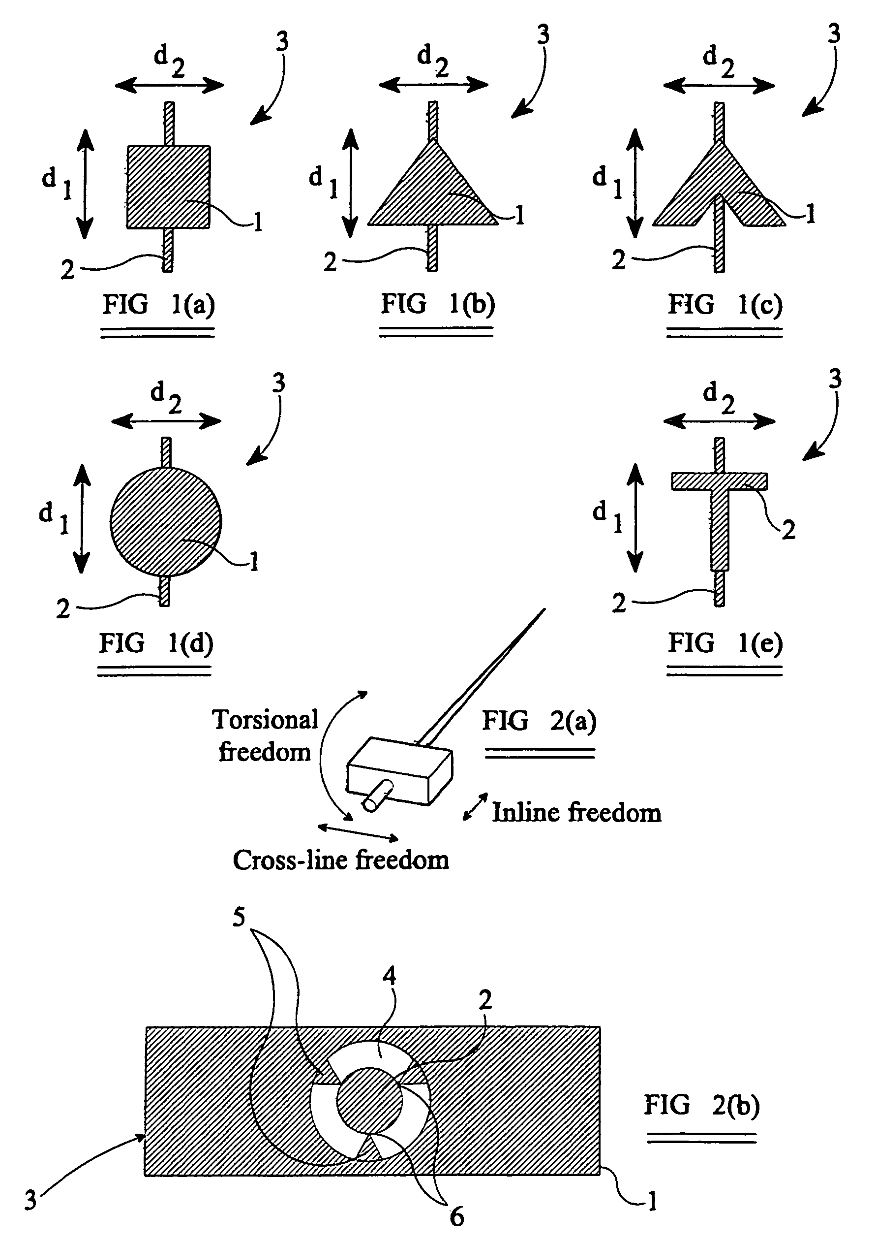
The present invention provides a seismic sensor housing and a seismic sensor for use on the earth's surface. The housing has a flat base that ensures good contact with the surface, regardless of the angle at which the seismic energy enters the cable. The housing is decoupled from the cable, which eliminates any influence of stiffness or tension in the cable on the sensor's measurements. The sensor can be used on any part of the earth's surface, such as the sea-bed, land, or the transition zone. The technical effects of the invention include improved seismic coupling and accurate recording of all components of the incident seismic data.

Problems solved by technology

All of the seafloor multi-component recording systems available to the market today have problems meeting this objective.
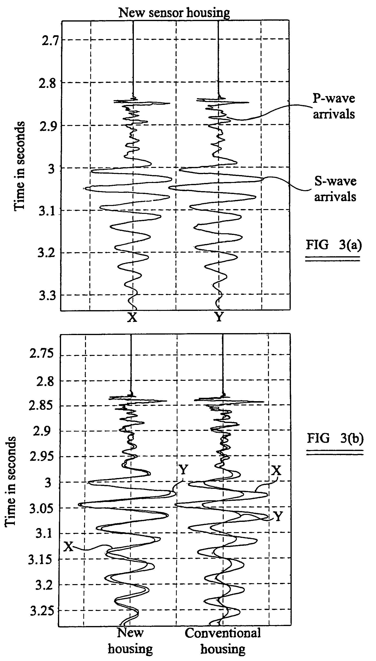
The principal problem that arises is the infidelity between the in-line (x-direction) and cross-line (y-direction) components of the elastic wavefield.
Some prior art sea-bed sensor housings also provide poor and inconsistent fidelity between the measured horizontal and vertical components of the measured seismic data.
This infidelity in the sensor response to different components of the wavefield leads to inaccurate survey results when the data is processed.
While the technique of applying a deconvolution operator can produce reasonable results if the vector infidelity is small, the distortion of the components of the wavefield during the measurement process is often too large for this technique to work.

Method used


Image

  • Housing for a seismic sensing element, and a seismic sensor
  • Housing for a seismic sensing element, and a seismic sensor
  • Housing for a seismic sensing element, and a seismic sensor

Examples


second embodiment

[0053]a sensor housing according to the present invention will be described with reference to FIGS. 4(a) to 4(b). In this embodiment, the sensor housing 9 consists of a first housing 10 and a second housing 11. The first housing 10 is intended to contain four sensing elements (not shown), for sensing the pressure and the three components of the elastic wavefield, and the second housing 11 is intended to contain electronic circuits associated with the sensing elements, for monitoring the sensing elements and processing their output signals. The electrical and electronic connections between the first housing 10 and the second housing 11 are enclosed in a water-tight tube 12 for protection.

[0054]The first and second housings 10, 11 are secured to the cable 2 by means of a clamp 13. The clamp 13 is in the form of an annulus, and, in use, is clamped to the cable 2 with the cable 2 passing through the interior of the clamp 13. The first and second housings 10, 11 are secured to the clamp ...


PUM


Abstract

A housing for a seismic sensing element (3) for use on the earth's surface comprises connecting means (5) for connecting the housing (3) to a support cable (2) so as to allow relative movement between the sensor housing (3) and the cable (2). This de-couples the sensor housing from the support cable, and improves the fidelity of the sensor.The connecting means (5) preferably comprises resilient connecting elements, to prevent the transmission of vibrations between the support cable and the sensor housing.The sensor housing (3) preferably has a flat base (1), so that there is good coupling between the sensor housing and the earth. Alternatively, the sensor housing can be fitted with a base member ((24a, 24b, 24c) that has at least one flat face (26, 26a, 26b, 26c).

Description

[0001]Applicant claims priority under 35 U.S.C. §120 from parent application Ser. No. 10 / 343,868, filed Oct. 8, 2003, now U.S. Pat. No. 7,260,024, which was a 35 U.S.C. §371 national stage filing from Patent Cooperation Treaty application number PCT / GB01 / 03612, filed Aug. 13, 2001, which in turn claimed priority from Great Britain patent application number 0020072.5, filed Aug. 16, 2000, from which Applicant has claimed foreign priority under 35 U.S.C. §119.BACKGROUND OF THE INVENTION[0002]1. Field of the Invention[0003]The present invention relates to a housing for a seismic sensing element, and in particular to such a housing intended to be disposed on the earth's surface. The term “earth's surface” as used herein includes the sea-bed, land, and the transition zone. The present invention also relates to a seismic sensor comprising one or more seismic sensing elements disposed within a housing according the present invention.[0004]A seismic sensor intended to be disposed, in use, o...

Claims


Application Information

Patent Timeline
Patent Type & Authority Patents(United States)
IPC IPC(8): G01V1/16G10K11/00G01V1/20G01V1/38
CPCG01V1/16G01V1/38G01V1/20G01V1/166
Inventor GOUJON, NICOLASMOBAREKEH, KAMBIZ IRANPOURMARTIN, JAMES EDWARDNAES, JOHAN FREDRIKVOLDSBEKK, RUNE SINDRE
Owner REFLECTION MARINE NORGE AS
Learn More