Touch and auditory sensors based on nanotube arrays
a nanotube array and sensor technology, applied in the direction of electrical/magnetically converting sensor output, measuring leads/probes, instruments, etc., can solve the problems of many difficulties in producing such a device, inability to make uniform devices, and inability to set a plurality of sensors on one chip
- Summary
- Abstract
- Description
- Claims
- Application Information
AI Technical Summary
Benefits of technology
Problems solved by technology
Method used
Image


Examples
example 1
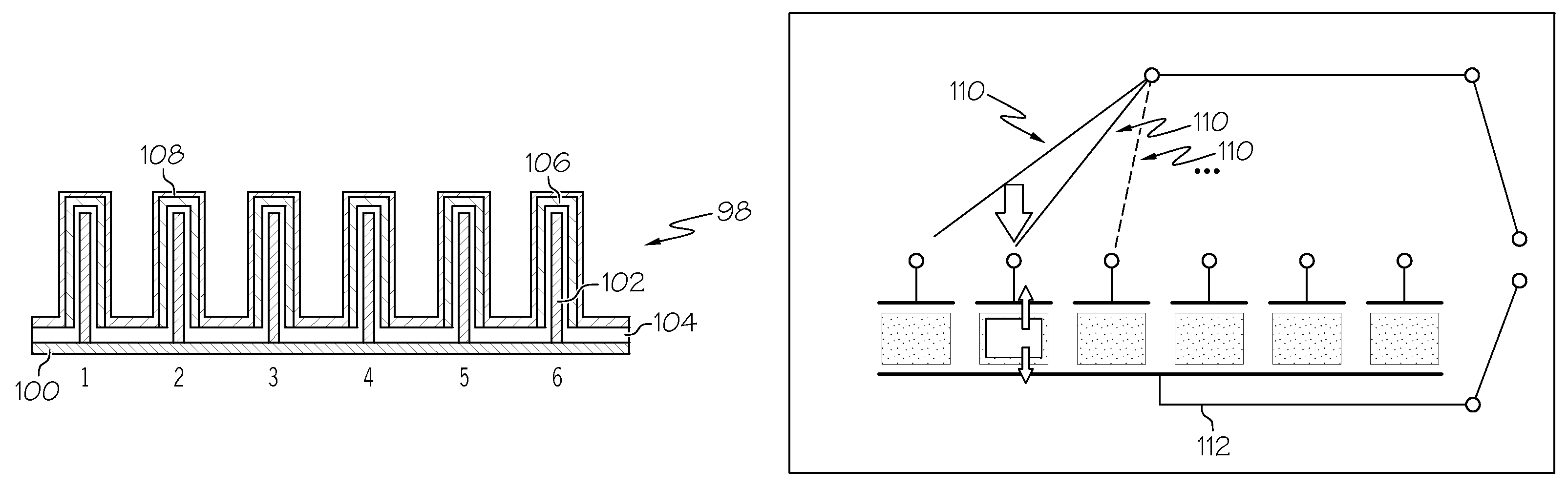
[0052]As shown schematically in FIGS. 8A and 8B, a touch sensor 98 was made using vertically aligned straight CNT arrays. The CNT arrays were prepared by a thermal CVD process at 800° C. using ferrocene as a catalyst and xylene as a carbon source. The CNT arrays were created on a semi conductive substrate (SiO2) and then transferred to an aluminum substrate 100. A connection between the aluminum substrate 100 and the CNT arrays was made using a carbon based adhesive. In particular, six individual CNT sensor electrodes 102 were supported by the aluminum substrate 100 and were made by cutting a 500 μm-long densely packed CNT array to the size of a 2 mm square individually. The outer walls of the CNT electrodes 102 were then coated by a thin layer of polyvinylidene fluoride (PVDF) 104 as a piezoelectric polymer. A thin gold layer was sputter-coated onto the PVDF-coating 104 to construct another electrode 106. Finally, the whole device was encapsulated with a thin layer of an elastomer ...
example 2
[0054]The Preparation of a Patterned Array of a Sensor
[0055]A patterned array of a sensor was prepared on an Al2O3 substrate, which had 16 individual sensor probes, as shown in FIG. 10A. A gold padding substrate was pre-laid down underneath of the sensor probes for addressing the sensor units. To support the growth of vertically aligned CNTs within each of the patterned sensor probes, chromium (Cr) was first selectively deposited into the patterned area shown in FIG. 10B on a pristine Al2O3 substrate by photolithographic patterning. Then, iron (Fe) catalyst was selectively deposited onto the small squared area 304 within the Cr-covered square patterned regions (FIG. 10B). Thereafter, the metal patterned substrate was inserted to a furnace to synthesize the CNT array. The synthesis of the CNT array was done under decreased pressure with flowing of an acetylene gas and a hydrogen gas at 750° C. A vertically aligned CNT array thus prepared is shown in FIG. 10C. The CNT array was grown ...
PUM
 Abstract
Description
Claims
Application Information
 - R&D
- Intellectual Property
- Life Sciences
- Materials
- Tech Scout
- Unparalleled Data Quality
- Higher Quality Content
- 60% Fewer Hallucinations
Browse by: Latest US Patents, China's latest patents, Technical Efficacy Thesaurus, Application Domain, Technology Topic, Popular Technical Reports.
© 2025 PatSnap. All rights reserved.Legal|Privacy policy|Modern Slavery Act Transparency Statement|Sitemap|About US| Contact US: help@patsnap.com