
Programmable fuel pump control

a fuel pump and control technology, applied in the direction of electrical control, process and machine control, instruments, etc., to achieve the effect of relatively small return fuel flow ra

Inactive Publication Date: 2010-08-10
FLUID CONTROL PRODS
View PDF31 Cites 13 Cited by
  • Summary
  • Abstract
  • Description
  • Claims
  • Application Information

AI Technical Summary

Benefits of technology

"The present invention is a programmable fuel pump control that can be used in both return-style and returnless fuel systems. It includes a diaphragm assembly with an adjustable flow restrictor between a normally open relief valve and a diaphragm assembly housed in an expansible fill chamber. The diaphragm assembly is set at a minimum pressure to allow fuel to flow constantly during engine operation. The system also includes sensors to measure fuel pressure, fuel temperature, and air pressure. The programmable control can adjust pump speed based on fuel demand, and it allows for the continuous flow of fuel through the fuel rail and back to the tank for purge purging without the need for fuel injectors. The system also includes an engine safety control relay that can shut down the fuel system in case of low fuel pressure or excessive fuel leakage. The technical effects of the invention include improved fuel system control and optimization of fuel pressure spikes."

Problems solved by technology

However, because the fill chamber is expansible, it can buffer fuel pressure spikes.

Method used


Image

  • Programmable fuel pump control
  • Programmable fuel pump control
  • Programmable fuel pump control

Examples


Embodiment Construction

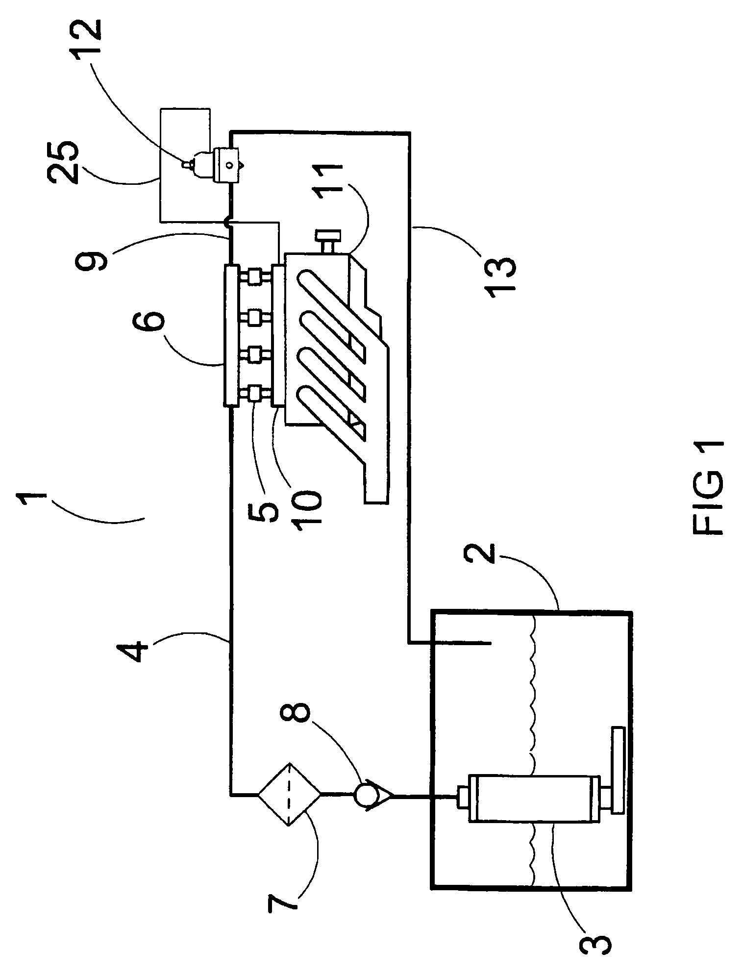
[0028]FIG. 4 illustrates a preferred embodiment return-style fuel delivery system 200 of the present invention for an engine with fuel injection. As shown in FIG. 4, fuel in tank 202 is pumped by the fuel pump 203 through check valve 208, fuel filter 207, fuel line 204 and on to the engine fuel rail 206. Fuel injectors 205 deliver fuel from fuel rail 206 into engine intake manifold 210 to be used by the engine. Excess fuel from the fuel rail 206 is passed through fuel line 209 to the programmable fuel pump control 251. When control 251 is employed as part of a return-style fuel system, fuel exiting fuel pump control 251 is returned back to tank 202 via return line 213.

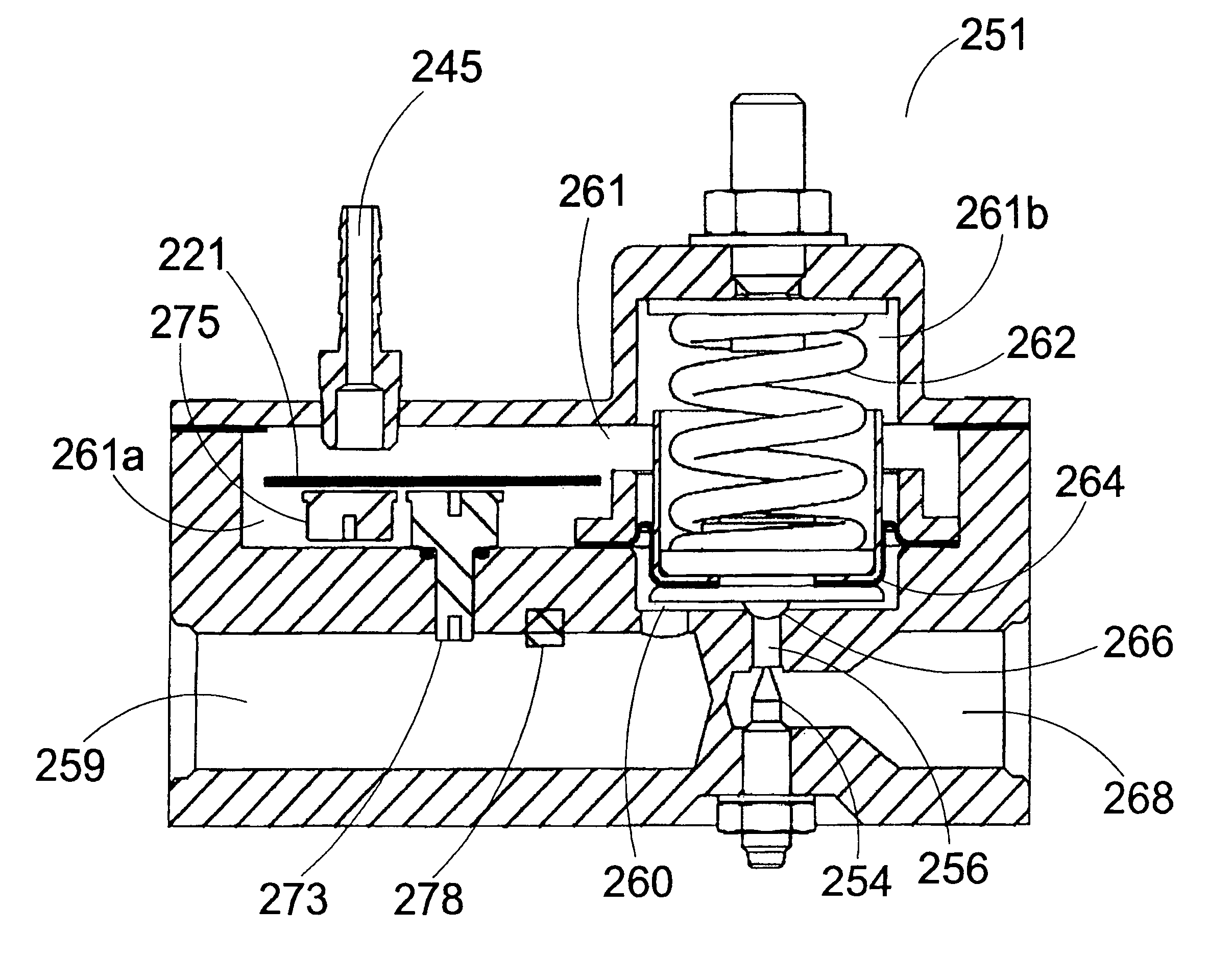
[0029]FIG. 5 depicts a preferred embodiment programmable fuel pump control. To provide for differential pressure analysis, fuel pump control 251 is fluidly connected to fuel rail 206 and engine intake manifold 210. In this respect line 209 delivers excess fuel from fuel rail 206 to fuel intake chamber 259 of pump contr...


PUM


Abstract

A programmable fuel pump control for a fuel system includes integral sensors, an expansible fill chamber and a return chamber. The control can be used in either a return-style of returnless fuel system. The expansible fill chamber is in fluid communication with the fuel rail. A restrictable fuel passage connects the fill chamber to a return chamber that in a return-style fuel system can be optionally connected to a return line. The control includes an integral pressure transducer measuring fuel pressure relative to intake manifold pressure and one or more adjunct sensors that allow real time control of a fuel pump speed, and therefore fuel pressure, as a function of engine performance.

Description

CROSS REFERENCE TO RELATED APPLICATION[0001]Not applicable.STATEMENT REGARDING FEDERALLY SPONSORED RESEARCH OR DEVELOPMENT[0002]Not applicable.SEQUENCE LISTING, TABLE OR COMPUTER PROGRAM ON COMPACT DISC[0003]Not applicable.FIELD OF INVENTION[0004]This invention relates generally to fuel systems and more particularly to fuel systems for fuel injected engines.BACKGROUND OF THE INVENTION[0005]The typical motor vehicle utilizes electronic fuel injection (EFI) to deliver fuel into the engine. The fuel injectors (solenoid valves) are electronically connected to an engine control module that controls the amount of fuel entering the engine via control of the solenoid valves. By changing the dwell time of the valves, the amount of fuel entering the engine can be controlled. Fluctuations in engine performance and operating conditions can affect fuel pressure in the fuel system and hence the amount of fuel entering the engine. There are essentially two types of EFI systems, return-style and re...

Claims


Application Information

Patent Timeline
Patent Type & Authority Patents(United States)
IPC IPC(8): F02D41/30
CPCF02D41/3082F02D41/32F02M37/0029F02M69/465F02M69/54F02D2200/0406F02D2200/0602F02D2200/703F02M37/10
Inventor SCHARFENBERG, ROBERT E.
Owner FLUID CONTROL PRODS
Learn More