
Parallel connection of inverters

a parallel connection and inverter technology, applied in the direction of ac-dc conversion, dc source parallel operation, electrical apparatus, etc., can solve the problems of residual errors, inability to easily and inability to correct large timing errors in the control of power switches. , to achieve the effect of simple and redundant parallel connection

Active Publication Date: 2010-08-10
VACON OY
View PDF14 Cites 24 Cited by
  • Summary
  • Abstract
  • Description
  • Claims
  • Application Information

AI Technical Summary

Benefits of technology

[0007]When aiming for a simple and redundant parallel connection it would be extremely advantageous if one optic fiber pair or one bi-directional optic fiber per device were sufficient.
[0009]The invention allows increasing the power handling capability of a frequency converter with parallel connections in numerous applications such that the impedance needed to equalize the currents is small. Owing to the general purpose usability also so-called open-loop applications can be easily implemented without an equalizing current adjustment. The main applications include the main drives of ships, wind power plants of >1 MW output, step-up transformers provided with a plurality of primary windings, and high-powered pumps in the medium-speed of rotation range.

Problems solved by technology

In order to equalize the currents, and thus losses, normally a so-called disbalance adjustment is used, with which the currents are balanced over a long time span, but which nevertheless is not capable of correcting large timing errors in the control of the power switches.
A drawback of the duplication method is also that the timing of the pulses cannot easily be corrected in order to minimize residual errors.

Method used


Image

  • Parallel connection of inverters
  • Parallel connection of inverters
  • Parallel connection of inverters

Examples


Embodiment Construction

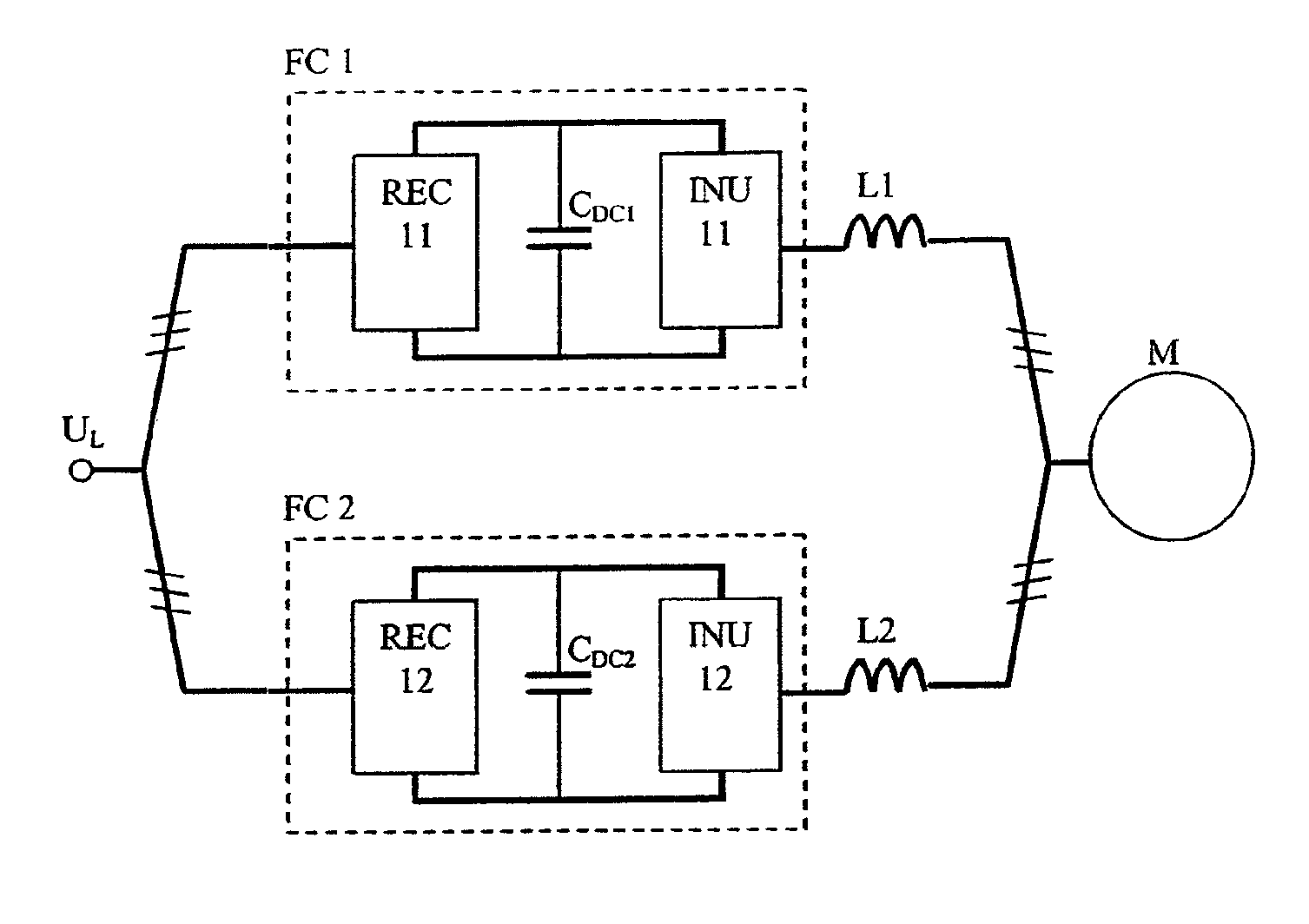
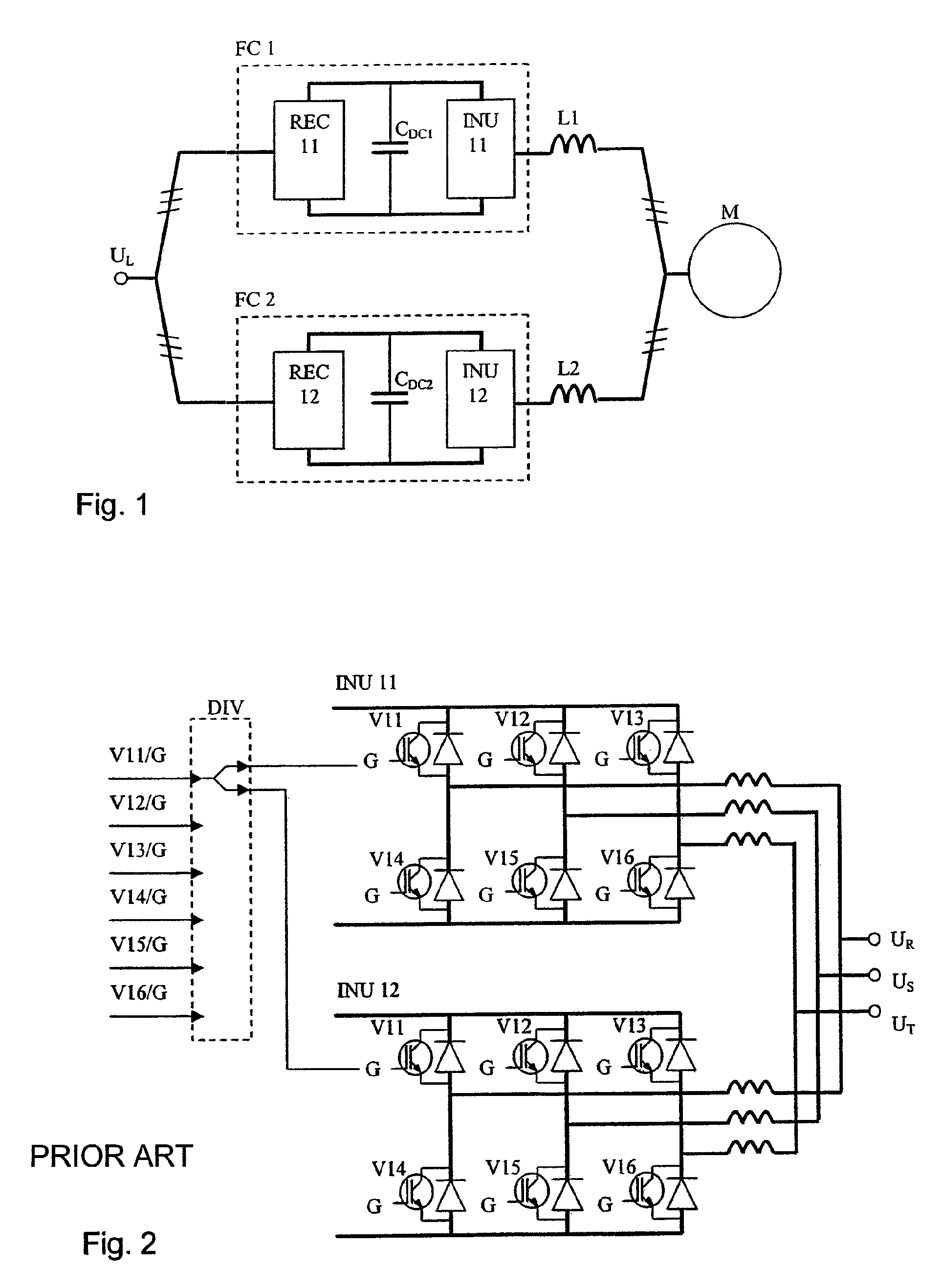
[0017]FIG. 1 presents a motor drive, in which a high-output three-phase alternating-current electric motor M, which can be an asynchronous motor or a synchronous motor, is supplied by two three-phase PWM frequency converters FC1 and FC2 connected to a three-phase network UL, in both of which is a rectifier bridge REC11, REC12, a DC-voltage intermediate circuit, in which is a capacitor CDC1, CDC2, and an inverter (INU-unit) INU11, INU12, in which is a full-wave bridge rectifier provided with semiconductor switches, such as IGBT, controlled by a gate, and its control. In the connection an equalizing impedance L1 and L2 has been added between the frequency converters.

[0018]FIG. 2 presents the parallel connection of inverter units according to prior art. The inverter units comprise the power switches V11-V16 and the diodes connected in parallel with them. The control pulses of the power switches formed by the common control unit in a parallel connection are divided into simultaneous gal...


PUM


Abstract

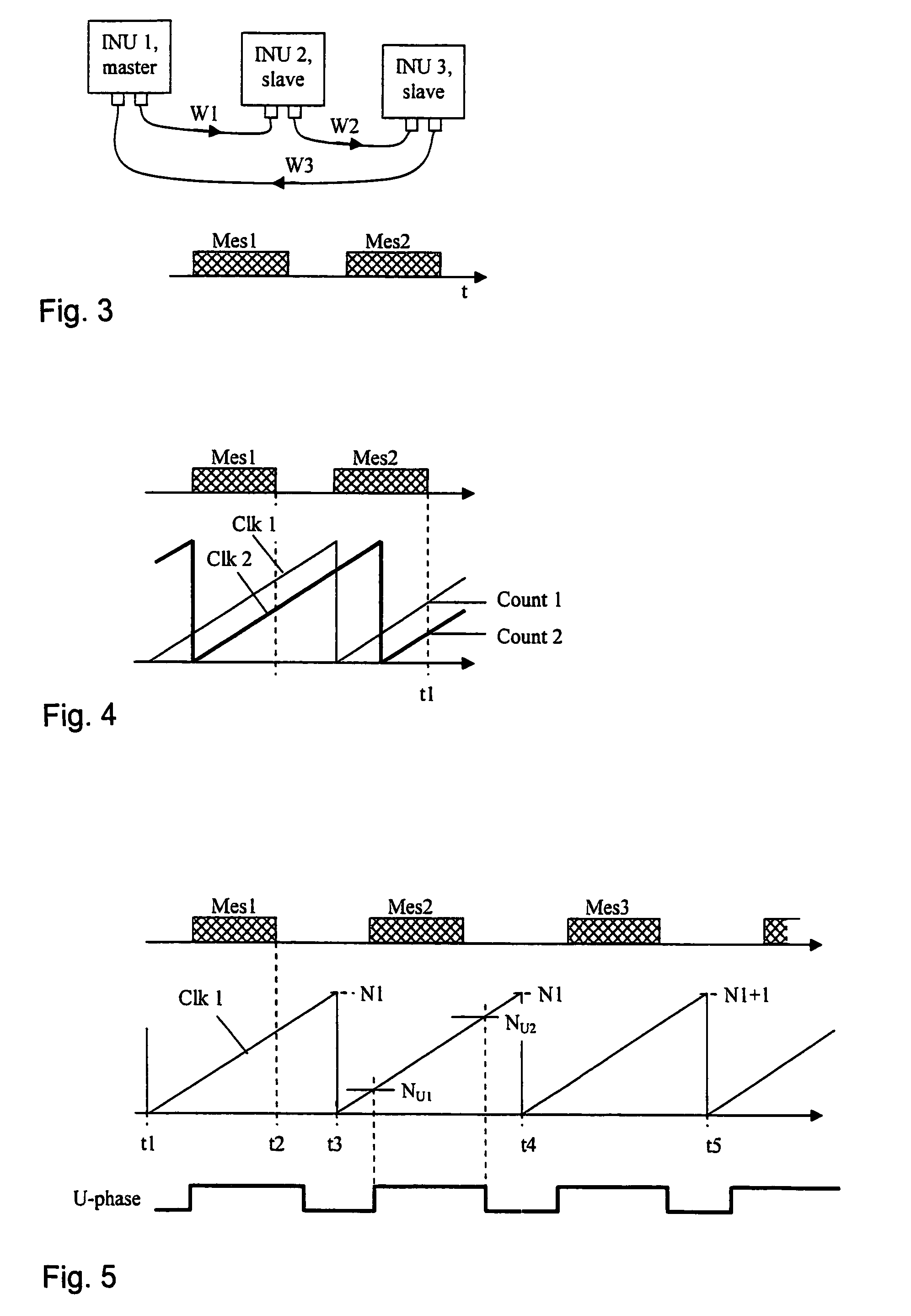
Method for synchronizing inverter units (INU11, INU12) that are connected in parallel and supply a motor, and a parallel connection arrangement, in which motor is either one winding, which is supplied by inverter units connected in parallel, or a plurality of parallel windings, in which each winding is supplied by its own inverter unit, in which parallel connection one inverter unit functions as a master and the others as slaves, in which method a telecommunications bus is arranged between the units, and in which each inverter unit has its own modulation cycle counter, which are synchronized with each other on the basis of telecommunications messages, preferably serial telecommunications messages. In the invention all the inverter units take into memory the value of their own modulation counter at the termination time of a telecommunications message (Mes2), the master inverter unit sends the reading of its own counter in the following message to the other inverter units, and the other inverter units correct the reading notified by the master on the basis of the readings of their own modulation counters in the direction that makes the counters operate as simultaneously as possible.

Description

FIELD OF TECHNOLOGY[0001]The object of the present invention is a method for controlling inverter units that are connected in parallel and controlled with pulse width modulation (PWM), e.g. frequency converters. More particularly an object of the invention is a method for synchronizing inverter units that are connected in parallel and supply an alternating-current electric motor and that are based on both synchronous and asynchronous space-vector-based pulse width modulation methods. The invention also relates to an arrangement for the parallel connection of inverter units.[0002]Parallel connection of frequency converters and their inverters is required in the control of motors of very high output power (e.g. >1 MW), because owing to the power components available the power handling capability of individual frequency converters is substantially smaller.[0003]The greatest problem with a parallel connection is how the pulse waveforms of the PWM output voltages can be synchronized s...

Claims


Application Information

Patent Timeline
Patent Type & Authority Patents(United States)
IPC IPC(8): H02M7/48H02J1/10
CPCH02M7/515H02M5/458H02M7/493H02M7/53873H02P2207/05
Inventor OLLILA, JAAKKOKUKKONEN, PASIRAJAKANGAS, KIMMOSTRANDBERG, STEFAN
Owner VACON OY
Learn More