
Rotorcraft skid undercarriage and a rotorcraft including such an undercarriage

a technology of rotorcraft and undercarriage, which is applied in the direction of rotocraft, aircraft components, and landing gear, etc., can solve the problems of explosive coupling, skid undercarriage, and relatively complex and heavy undercarriage described in those documents, so as to reduce the (angular) stiffness of the aircraft roll, increase the deformation capacity, and reduce the effect of angular stiffness

Inactive Publication Date: 2010-08-10
EUROCOPTER
View PDF10 Cites 5 Cited by
  • Summary
  • Abstract
  • Description
  • Claims
  • Application Information

AI Technical Summary

Benefits of technology

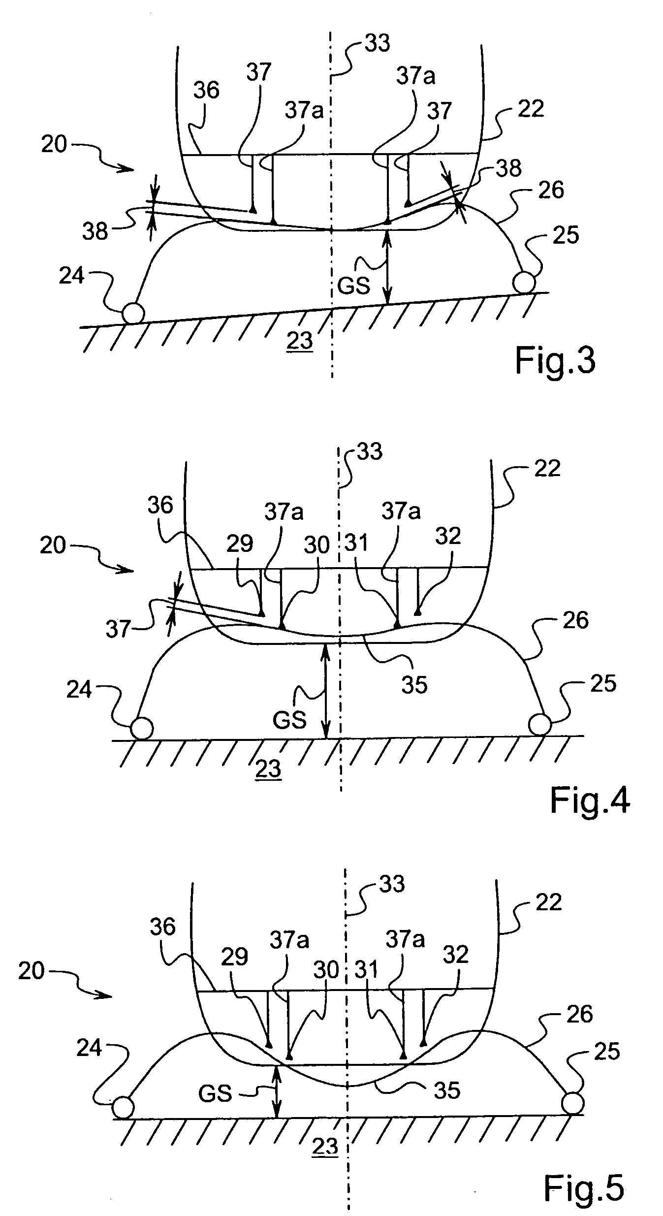
[0022]Under such circumstances in particular, the first connection means preferably further comprise a resilient band member associated with each first saddle to co-operate therewith to surround the cross-member, while allowing the cross-member to move vertically relative to the saddle and inside the saddle, as is made possible by the elastic deformation of the band member which serves to keep the undercarriage in place when the rotorcraft is in flight.
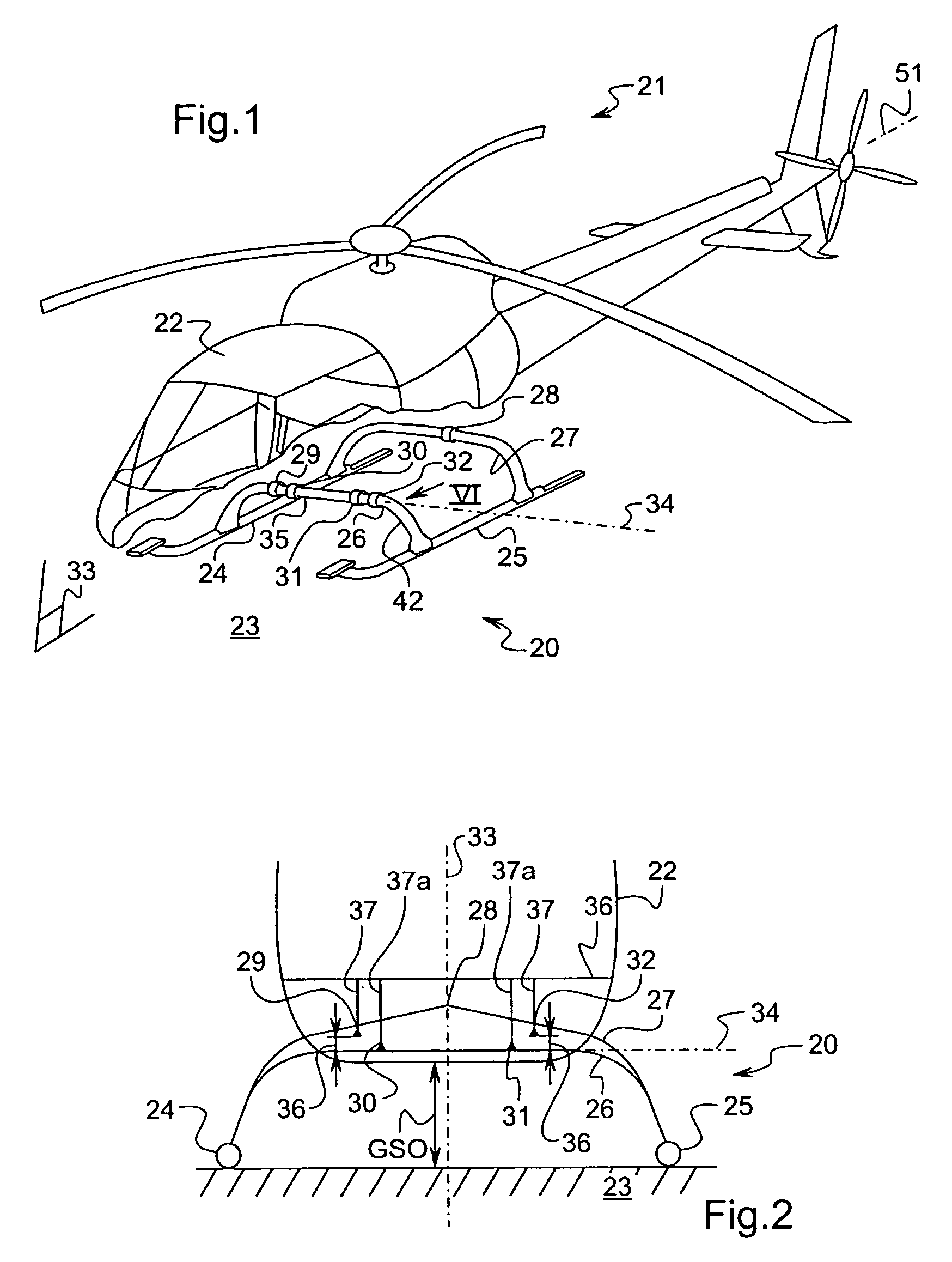
[0028]In particular, an undercarriage is proposed in which the generally tubular cross-member (of closed profile) presents smaller second moment of area in a central portion than in two side (end) portions extending on either side of the central portion. This encourages “controlled” deformation of the cross-member, and in particular of its central portion; this increased capacity for deformation (elastic and plastic) of the cross-member serves both to reduce the (angular) stiffness in roll of the aircraft resting on its undercarriage, and also its stiffness along the vertical axis.

Problems solved by technology

When the undercarriage is subcritical, no frequency crossing occurs up to nominal speed, but a change in the weight, in the roll inertia, or in the position of the center of gravity can lead to a frequency crossover occurring close to nominal speed, thereby creating coupling that is explosive.
The undercarriages described in those documents are relatively complex and heavy.
Another unsolved problem is that of providing a skid undercarriage that is relatively unsophisticated while nevertheless reducing the load factor imposed on passengers during landing, as compared with rigid undercarriages.

Method used


Image

  • Rotorcraft skid undercarriage and a rotorcraft including such an undercarriage
  • Rotorcraft skid undercarriage and a rotorcraft including such an undercarriage
  • Rotorcraft skid undercarriage and a rotorcraft including such an undercarriage

Examples


Embodiment Construction

[0041]With reference to FIG. 1 in particular, the present invention applies specifically to a skid undercarriage 20 fitted to a helicopter 21 whose airframe 22 can rest on the ground 23 via an undercarriage.

[0042]In the meaning of the present application, the term “skid undercarriage” designates an undercarriage comprising two skids, skis, or floats given overall references 24 and 29 and that extend substantially along the longitudinal axis 51 of the rotorcraft.

[0043]The skids 24 and 25 are connected together by a front cross-member 26 and by a rear cross-member 27, each of these cross-members presenting two downwardly-curved end portions. Each outer or lateral end of the cross-members is connected to one of the skids.

[0044]With reference to FIGS. 1 and 2, the rear cross-member 27 receives single connection means 28 for connection with the fuselage (airframe) of the helicopter, in a bearing zone or point located in the middle of the cross-member 27.

[0045]The front cross-member 26 re...


PUM


Abstract

The invention relates to a rotorcraft (21) comprising a fuselage (22) and an undercarriage (20) having skids (24, 25) interconnected by at least one cross-member (26, 27), together with connection means for connecting the cross-member to the fuselage and presenting angular stiffness that varies with varying sinking (E) of the undercarriage as a result of contact with the ground (23).

Description

[0001]The present invention relates to improvements to skid undercarriages for rotorcraft, and to rotorcraft including such an undercarriage.[0002]The technical field of the invention is that of manufacturing helicopters.BACKGROUND OF THE INVENTION[0003]In addition to allowing a rotorcraft to be maintained in a stable position or to slide on the ground, the undercarriage or landing gear has as its main function that of dissipating at least part of the energy of the impact that is caused by the rotorcraft landing.[0004]This energy is absorbed by friction against the ground, by deformation of the undercarriage, and of its connections with the airframe of the rotorcraft, and where appropriate by shock absorbers. Such deformation is made possible by the parts of the undercarriage being elastic.[0005]The rotorcraft standing on its undercarriage can be thought of as a suspended weight. The resulting mechanical system presents resonant modes of deformation that correspond to resonant frequ...

Claims


Application Information

Patent Timeline
Patent Type & Authority Patents(United States)
IPC IPC(8): B64C25/52B64C25/00B64C25/58
CPCB64C25/52B64C2025/325
Inventor BIETENHADER, CLAUDE
Owner EUROCOPTER
Learn More