Method for igniting combustion of fuel in a combustion chamber of an engine, associated device and engine

a combustion chamber and combustion chamber technology, applied in the direction of non-adjustable resistors, resistors, combustion processes, etc., can solve the problems of only insignificant optimization of the combustion process, increased production costs due to the required catalyst materials, and limited combustion propagation speed, so as to reduce fuel consumption and reduce pollutant emission, the effect of optimizing the combustion characteristi

Active Publication Date: 2010-08-10
MWI MICRO WAVE IGNITION
View PDF19 Cites 14 Cited by
  • Summary
  • Abstract
  • Description
  • Claims
  • Application Information

AI Technical Summary

Benefits of technology

[0008]An object of the present invention is to provide a process for ignition of the combustion of fuel in the combustion space of an engine, the pertinent ignition device and the pertinent engine which overcome the disadvantages of the prior art. In particular, ignition will take place according the present invention such that the combustion characteristic is optimized, especially with reduced fuel consumption and reduced pollutant emission at a given power.
[0013]The supplied microwave energy heats the fuel droplets present in the fuel-air mixture up to the ignition point, and thus, ignites the mixture. In contrast to the prior art, in the present invention the production of a plasma is avoided.
[0018]In one preferred embodiment of the present invention, a coupling means is between the microwave source and the microwave window. The coupling means transmits the microwaves sent by the microwave source to the microwave window, but does not transmit the microwaves reflected by the combustion space back into the microwave source. In particular, this coupling means can have a triple port, especially a circulator with a microwave source connected to its first port, a microwave window connected to its second port and a preferably passive microwave consumer connected to its third port. The circulator relays microwave energy from the microwave source to the combustion space, and at the same time diverts the microwave energy radiated back by the combustion space to the passive microwave consumer which absorbs the microwave energy reflected by the combustion space. In this way, the microwave source is protected against reflected microwave radiation. The circulator can contain a gas-filled discharger to improve the function of reducing the microwave energy which has been radiated back.
[0022]By using several microwave pulses, the fuel droplets present in the fuel-air mixture are heated gradually until the ignition temperature is reached. In this way, basically unwanted different temperature regions in the combustion space are avoided since the gradual increase of the temperature leads to a more uniform, and thus, ultimately practically simultaneous and uniform ignition of the entire mixture in the combustion space. Moreover, basically likewise unwanted plasma generation is prevented by the repeated pulses.

Problems solved by technology

Subsequently combustion propagates with an admittedly limited velocity.
The disadvantages involve the production costs due to the required catalyst materials being increased, and the combustion process only insignificantly being optimized.
It is common to the two-chamber ignition processes that they require high construction, and thus, production cost.
This arrangement leads to considerable construction effort, especially with respect to the engine pistons which move up and down.
Moreover, the microwave transmitter limits the path of piston motion in the engine.
In this way, the complexity of the ignition device and of the ignition process as well as the pertinent engine is further increased.
The known processes commonly require complex, and thus, expensive and high-maintenance structures.
Moreover, they have only a limited service life.
The efficiency of the combustion process, and therefore, of the engine driven by it are limited.
In addition, the emission of pollutants is not adequately reduced.
The lower combustion temperature also leads to increased pollutant emission.

Method used


Image

  • Method for igniting combustion of fuel in a combustion chamber of an engine, associated device and engine
  • Method for igniting combustion of fuel in a combustion chamber of an engine, associated device and engine
  • Method for igniting combustion of fuel in a combustion chamber of an engine, associated device and engine

Examples


Embodiment Construction

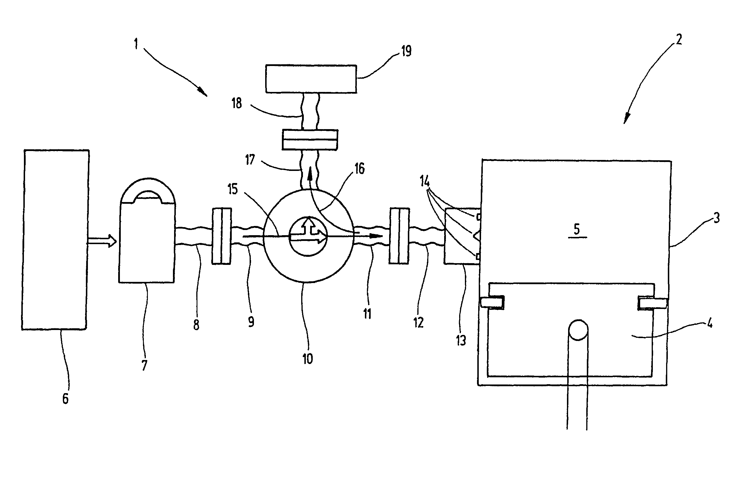
[0028]FIG. 1 schematically shows the structure of an ignition device 1 according to an exemplary embodiment of the present invention for a schematically shown engine 2. Only the cylinder 3 and the piston 4 which moves up and down in it are shown. The piston 4 and the cylinder 3 border the combustion space 5 in which ideally a fuel-air mixture is uniformly distributed. In FIG. 1 the piston 4 is roughly at top dead center.

[0029]The ignition device 1 comprises a pulsed high voltage power pack 6 with energy which drives the microwave source 7. A first piece of preferably flexible microwave line 8 is connected by a flange to a first connecting flange 9 of the circulator or coupler 10. On the side opposite the first connecting flange 9, the circulator 10 has a second connecting flange 11 connected by a flange to a second, preferably flexible microwave line 12 leading to the microwave window 13.

[0030]The microwave window 13 is fixed on the jacket surface of the cylinder 3 such that the mic...


PUM


Abstract

A method ignites the combustion of fuel in a combustion chamber (5) of engine (2), by introducing microwave radiation into the combustion chamber (5). The microwave radiation is produced in a microwave source (7) on the outside of the combustion chamber (5). The introduced microwave radiation is absorbed by the fuel distributed in the combustion chamber (5). The supply of energy, in the fuel, arising from absorption, distributes combustion in a large-volume in the combustion chamber (5), preferably in the entire combustion chamber (5) and in a homogenous manner, and is essentially simultaneously ignited. An associated ignition device (1) and an associated engine (2) are also provided.

Description

FIELD OF THE INVENTION[0001]The present invention relates to a process for igniting the combustion of fuel in the combustion chamber or combustion space of an engine, to an associated ignition device and to an associated engine.BACKGROUND OF THE INVENTION[0002]Because the ignition process has a considerable effect on the efficiency of an internal combustion engine, and especially at a given engine output also largely determines the fuel consumption and pollutant emission, in the past extensive efforts have been made to optimize the ignition process. The currently most common ignition devices use spark plugs which ignite the fuel-air mixture. These spark plugs can have one or more electrodes. Each of these electrodes produces an ignition spark which ignites the fuel-air mixture in the immediate vicinity of the electrode. Combustion begins accordingly first in a very small starting volume around the electrodes of the spark plugs. Subsequently combustion propagates with an admittedly l...

Claims


Application Information

Patent Timeline
Patent Type & Authority Patents(United States)
IPC IPC(8): F02B19/00F02P23/00F02P23/04
CPCF02P23/045F02P23/00F02P23/04
Inventor GALLATZ, VOLKERHIRSCH, NIKITATARASOVA, IRINA
Owner MWI MICRO WAVE IGNITION
Why Eureka
Try Eureka