
Full CMOS min-sum analog iterative decoders

an iterative decoder and full cmos technology, applied in analogue computers, instruments, analog and hybrid computing, etc., can solve the problems of high complexity, high cost, and difficult implementation of a large number of high-precision digital multipliers, and achieve the effect of simple design and low fabrication cos

Inactive Publication Date: 2010-08-03
BANIHASHEMI AMIR +1
View PDF7 Cites 15 Cited by
  • Summary
  • Abstract
  • Description
  • Claims
  • Application Information

AI Technical Summary

Benefits of technology

The proposed solution provides high precision and reduced complexity, enabling efficient implementation of min-sum decoders with lower power consumption and improved accuracy, suitable for a wide range of iterative coding schemes, including LDPC, turbo, convolutional, and block codes, while being more affordable and practical.

Problems solved by technology

There are a wide variety of iterative decoding algorithms, each resulting in a different performance / complexity trade-off.
Among these, sum-product (SP), also referred to as belief propagation, performs the best but is considered to be the most complex to implement.
In its original form, SP requires basic operations of addition and multiplication of real numbers, and thus the name “sum-product.” While implementing adders is rather straightforward and does not require much power and area in an integrated circuit, implementing a large number of high precision digital multipliers is more challenging.
However, the BiCMOS technology has a complex fabrication process compared to standard CMOS and this translates into higher cost.
Sub-threshold circuits in general have the advantage of consuming a very small amount of power, but often suffer from low speed, mismatch problems and low accuracy.

Method used


Image

  • Full CMOS min-sum analog iterative decoders
  • Full CMOS min-sum analog iterative decoders
  • Full CMOS min-sum analog iterative decoders

Examples


Embodiment Construction

Min-Sum Decoding Algorithm

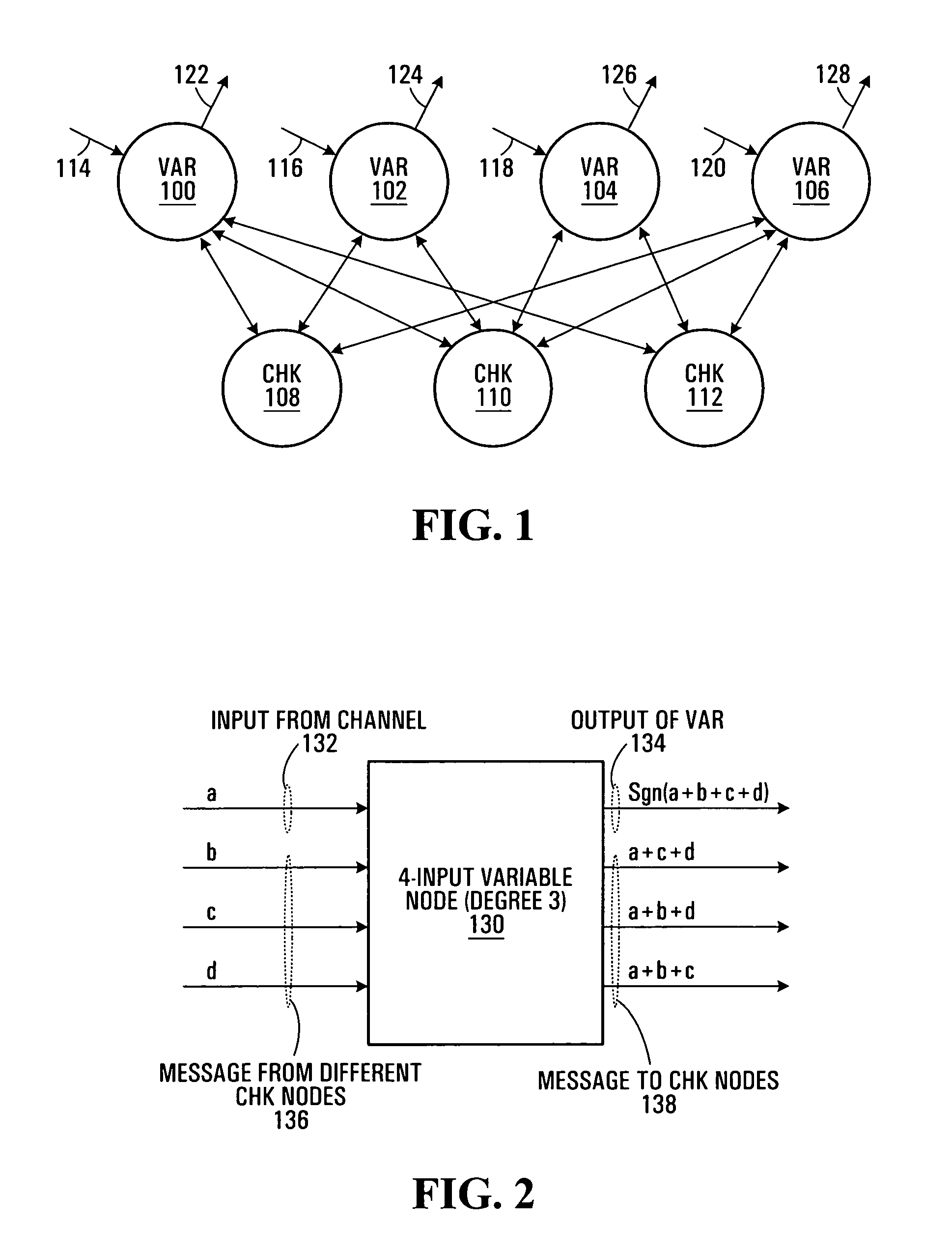
[0071]To explain the min-sum algorithm, binary LDPC codes will be considered together with the bipartite graph that represents the code through its parity-check equations, referred to as a “Tanner graph”. See for example Tanner, R. M., “A recursive approach to low-complexity codes,” IEEE Trans. Inform. Theory, vol. 27, pp. 533-547, September 1981.

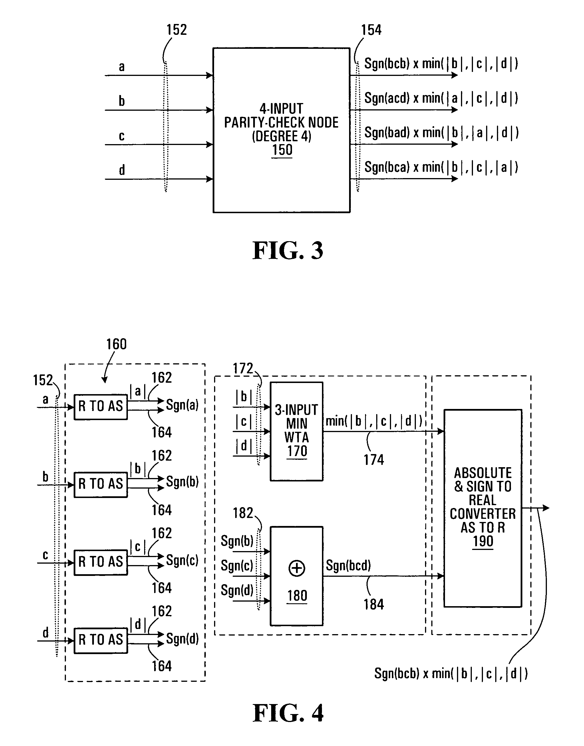
[0072]There are two sets of nodes in a Tanner graph: 1) variable nodes representing code bits, and 2) check nodes representing parity-check equations. To implement the min-sum algorithm in such a graph, two types of computational modules are required: one for variable nodes (VAR) and the other for check nodes (CHK). The operations performed in VAR and CHK modules depend on the representation of soft information (messages that are passed among CHK and VAR nodes through edges).

[0073]Referring first to FIG. 1, shown is an example of a Tanner graph. This Tanner graph has four VAR nodes 100,102,104,106 and three CHK nod...


PUM


Abstract

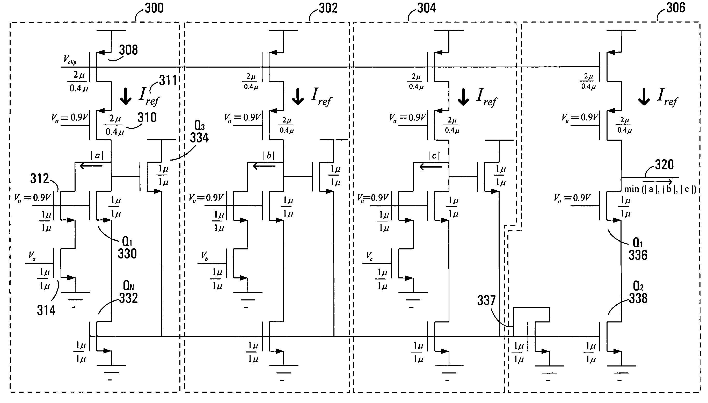
Analog iterative decoders are provided that are based on the so-called min-sum algorithm (also referred to as max-sum or max-product, Max-Log-MAP or BP-based decoding) and can be used to decode powerful coding schemes such as low-density parity-check (LDPC) codes and turbo codes. The circuits can be implemented by standard CMOS technology, which means lower fabrication cost and / or simpler design compared to previously reported analog iterative decoders that are based on BiCMOS or sub-threshold CMOS technology. Soft information is passed among variable nodes and parity-check nodes. A low-voltage high-swing Max WTA circuit is also provided. The circuit can be implemented by short channel MOSFET transistors and yet provide a reasonably high degree of accuracy. Applications include soft computing, and analog signal processing, in general. A Min WTA circuit can also be built based on this circuit by subtracting the input currents from a large reference current.

Description

FIELD OF THE INVENTION[0001]The invention relates to analog iterative decoders.BACKGROUND OF THE INVENTION[0002]In recent years, there has been much excitement in the digital communications and coding community about a class of error correcting codes which are very powerful and yet can be decoded practically using iterative algorithms. Two well-known examples are turbo codes and low-density parity-check (LDPC) codes.[0003]See for example Berrou, C., and Glavieux A., and Thitimajshima, P. “Near Shannon limit error-correcting coding: turbo codes,” in Proc. IEEE ICC'93, Geneva, Switzerland, 1993, pp. 1064-1070 and Gallager, R. G., “Low-density parity check codes,” IRE Trans. Inform. Theory, vol. 8, pp. 21-28 January 1962.[0004]The iterative algorithms can be most naturally described using graph representations of the codes. The execution of the algorithms can be described as performing certain computations at the nodes of the graph and passing real messages (soft information) along the...

Claims


Application Information

Patent Timeline
Patent Type & Authority Patents(United States)
IPC IPC(8): G06G7/00H03M13/11
CPCH03M13/1105H03M13/6597H03M13/2957H03M13/3905
Inventor BANIHASHEMI, AMIRHEMATI, SAIED
Owner BANIHASHEMI AMIR
Learn More