
Multi-gas flow sensor with gas specific calibration capability

a multi-gas flow sensor and calibration capability technology, applied in the field of sensor methods and systems, can solve the problems of complex calibration routines, limited sensing and signal conditioning capabilities of prior art sensing applications, and inability to accurately calculate the mass flow of different gases

Active Publication Date: 2010-08-03
HONEYWELL INT INC
View PDF9 Cites 20 Cited by
  • Summary
  • Abstract
  • Description
  • Claims
  • Application Information

AI Technical Summary

Benefits of technology

[0013]Additional correction factors to the processed signal outputs can be utilized depending on the measuring system, which require changes when the gas type also changes. Important measurands for accurately calculating the mass flow of different gases is: which gas is in the flow channel, the absolute temperature and the barometric pressure. Humidity can also be processed and may be used in the further calculations of the gas mass flow. The combi sensor output is provided to a conditioning microcontroller where the information can be processed into an accurate output signal for specific gas output. The multi-gas flow sensor with gas specific calibration disclosed herein can therefore provide a calibrated coarsely conditioned signal output for various known gases.

Problems solved by technology

The majority of prior art sensing applications possess limited sensing and signal conditioning capabilities.
Such sensing applications utilize multiple sensors, complex calibration routines and expensive micro-controllers / PLCs to condition basic flow signals from the sensor, regardless of the quantity being measured by the sensor.
This approach results in a complex system calibration, which leads to an increase in processing time and often produces inaccurate results.
Additionally, the installation costs for packaging individual sensors for such application increases, which further enlarges the size of the final sensor package.

Method used


Image

  • Multi-gas flow sensor with gas specific calibration capability
  • Multi-gas flow sensor with gas specific calibration capability
  • Multi-gas flow sensor with gas specific calibration capability

Examples


Embodiment Construction

[0017]The particular values and configurations discussed in these non-limiting examples can be varied and are cited merely to illustrate at least one embodiment and are not intended to limit the scope thereof.

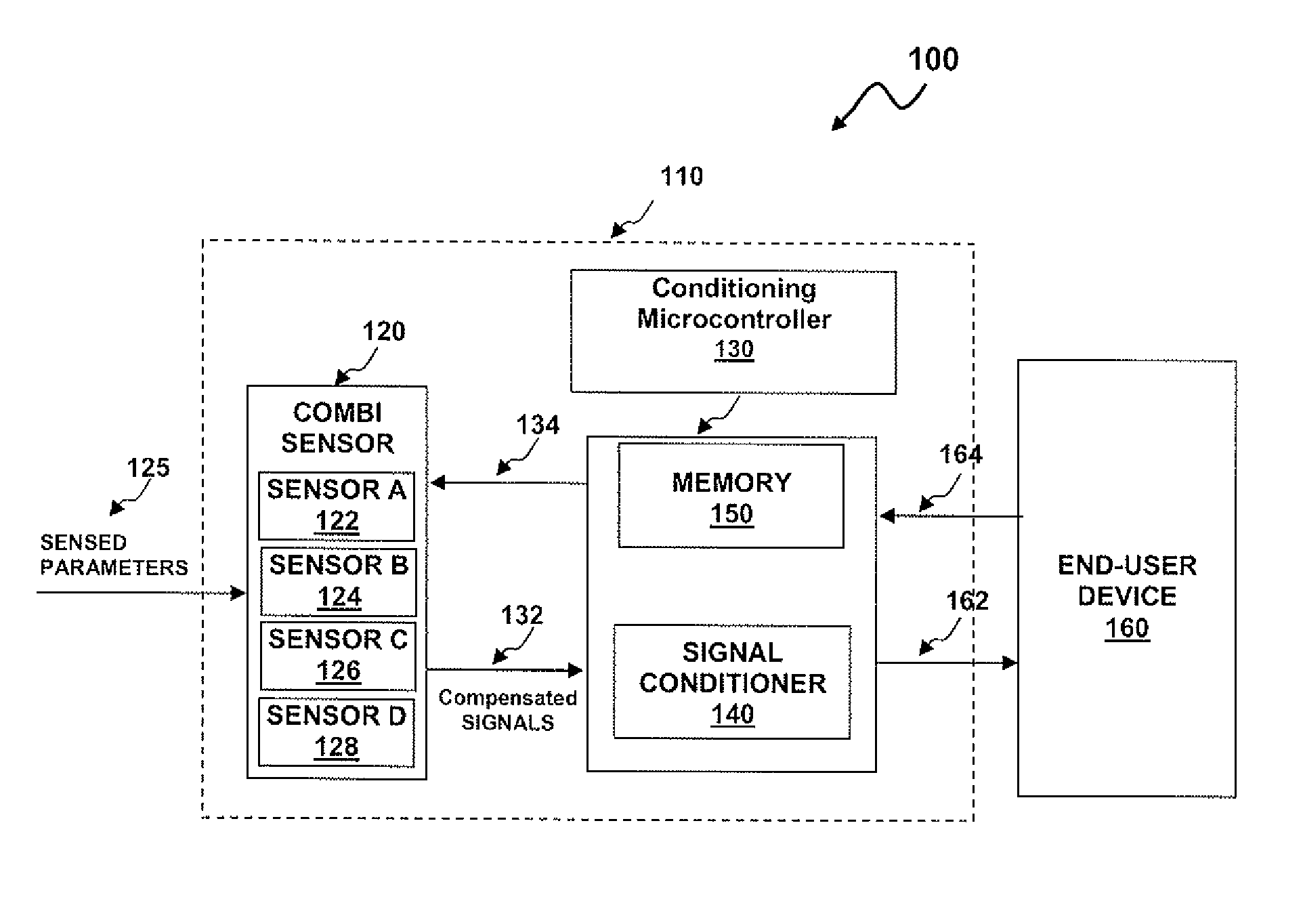
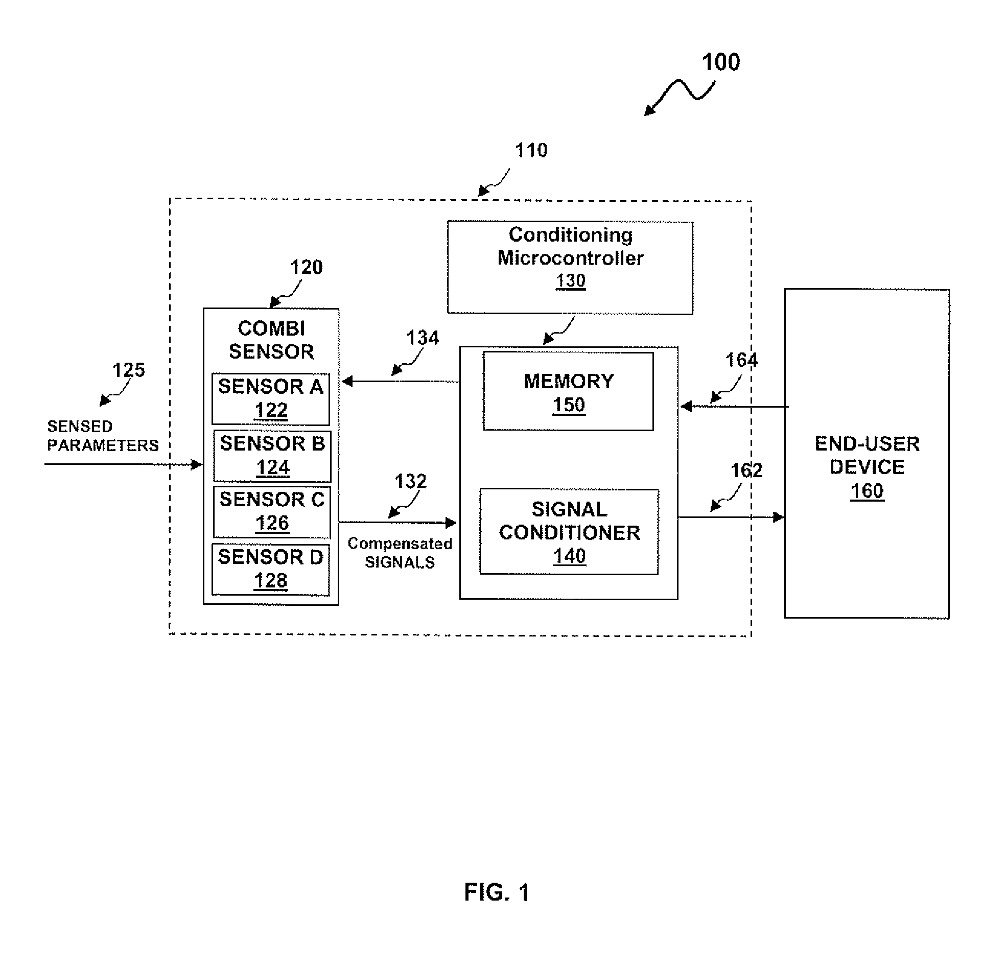
[0018]FIG. 1 illustrates a block diagram 100 of a flow sensor apparatus 110, which can be utilized for providing a calibrated gas / gas-mixture or liquid specific conditioned output, in accordance with a preferred embodiment. The flow sensor apparatus 110 is connected to one or more flow sensors within sensed parameters 125 and contains sensor processing ability. The flow sensor apparatus 110 is also connected to the end-user device 160. The flow sensor apparatus 110, in one embodiment, can be implemented as an Application Specific Integrated Circuit (ASIC) “combi sensor” apparatus 120 and a conditioning microcontroller 130 comprised of a signal conditioner 140 and non-volatile memory 150. It is important to note, however, that a combi sensor represents merely one possible implem...


PUM


Abstract

A multi-gas / gas-mixture or liquid flow sensor apparatus utilizing a specific media calibration capability. The flow sensor can be coupled with an Application Specific Integrated Circuit (ASIC) that incorporates a signal conditioner and a memory module. The signal conditioner provides a high order calibration and signal processing of flow signals from the sensor to a processed signal output representative of the flow. The processed signal output can be stored in the memory module. A correction factor can be calculated and stored in the memory module in response to the stored values of the processed signal output, which tends to linearize the relationship between the flow rate and the processed signal output of a measuring system. The correction factor and / or the processed signal output provided by the signal conditioner can be utilized by the measuring system.

Description

TECHNICAL FIELD[0001]Embodiments are generally related to sensor methods and systems. Embodiments are also related to combi sensors for measuring multiple measurands. Embodiments are additionally related to multi-gas flow sensors.BACKGROUND OF THE INVENTION[0002]Flow sensors are utilized in a variety of fluid-sensing applications for detecting the movement of fluids, which may be in gaseous (e.g., air) or liquid form. A gas mass flow sensor is one example of a flow sensor. Examples of gas sensing applications utilizing mass gas flow sensors include anesthesia gas mixers employed in medical applications, high-end welding equipment utilized in industrial applications, and gas chromatography detectors and controllers implemented in instrumentation applications. Typical sensor instrumentation utilized in such applications includes, for example, one or more simultaneous measurand to make calculations for sensor measurement. This is currently achieved by either using multiple sensors with...

Claims


Application Information

Patent Timeline
Patent Type & Authority Patents(United States)
IPC IPC(8): G01F25/00
CPCG01F15/022G01F25/0007G01F15/043G01F25/10
Inventor BEY, PAUL PREHNGEHMAN, RICHARD
Owner HONEYWELL INT INC
Learn More